


Chapter 2 2-11
Quick Start: Learning How to Make Measurements
Learning to Make Transmission Measurements
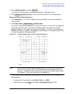
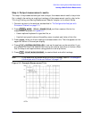
5. Press and enter .
The analyzer now calculates the bandwidth between −6 dB power levels.
6. Press when you are finished with this measurement.
Measuring Out-of-Band Rejection.
1. Press . The marker appears where you placed it during the bandwidth
measurement.
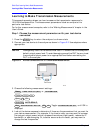
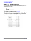
2. Press .
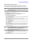
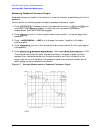
The marker automatically searches for the minimum point on the trace. The frequency
and amplitude of this point, relative to the delta symbol in the center of the filter
passband, appear in the upper-right corner of the display. This value is the difference
between the maximum power in the passband and the power in the rejection band, that
is, one of the peaks in the rejection band.
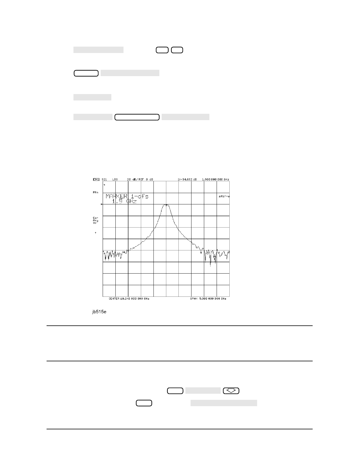
Figure 2-6 Example Measurement of Out-of-Band Rejection
NOTE You can use the marker search mode to search the trace for the maximum
point or for any target value. The target value can be an absolute level (for
example, −3 dBm) or a level relative to the location of the small delta symbol
(for example: −3 dB from the center of the passband).
3. If your measurement needs some noise reduction, you can reduce the IF bandwidth or
add averaging.
• To reduce the IF bandwidth, press .
• To add averaging, press , then toggle to ON.
WIDTH VALUE
−6 x1
Marker
MARKER all OFF
MARKER 1
MKR ZERO
Marker Search
SEARCH: MIN
Avg
IF BW [ ]
Avg
AVERAGING on OFF