


2-20 Chapter2
Quick Start: Learning How to Make Measurements
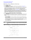
Learning to Make Reflection Measurements
Measuring S
11
and S
22
or Reflection in a Polar Format.
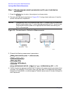
1. Press .
2. Press to reposition the trace, as shown in Figure 2-14.
The analyzer shows the results of an S
11
or reflection measurement with each point on
the polar trace corresponding to a particular value of both magnitude and phase. The
center of the circle represents a coefficient (Γ) of 0, (that is, a perfect match or no
reflected signal). The notation 2U FS or 2 units full scale indicates that the
outermost circumference of the scale shown in Figure 2-14 represents ρ = 2.00, or 200%
reflection. The phase angle is read directly from this display. The 3 o'clock position
corresponds to zero phase angle, (that is, the reflected signal is at the same phase as the
incident signal). Phase differences of 90°, 180°, and −90° correspond to the 12 o'clock,
9 o'clock, and 6 o'clock positions on the polar display, respectively.
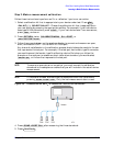
3. Press .
4. Turn the front panel knob to position the marker at any desired point on the trace, then
read the frequency, linear magnitude and phase in the upper right-hand corner of the
display.
• Choose if you want the analyzer to show the linear magnitude and the
phase of the marker.
• Choose if you want the analyzer to show the logarithmic magnitude and
the phase of the active marker. This is useful as a fast method of obtaining a reading
of the log-magnitude value without changing to log-magnitude format.
• Choose if you want the analyzer to show the values of the marker as a
real and imaginary pair.
NOTE You can also enter the frequency of interest, from either the numeric keypad
or the optional attached keyboard, and read the magnitude and phase at that
point.
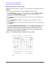
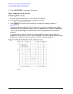
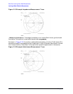
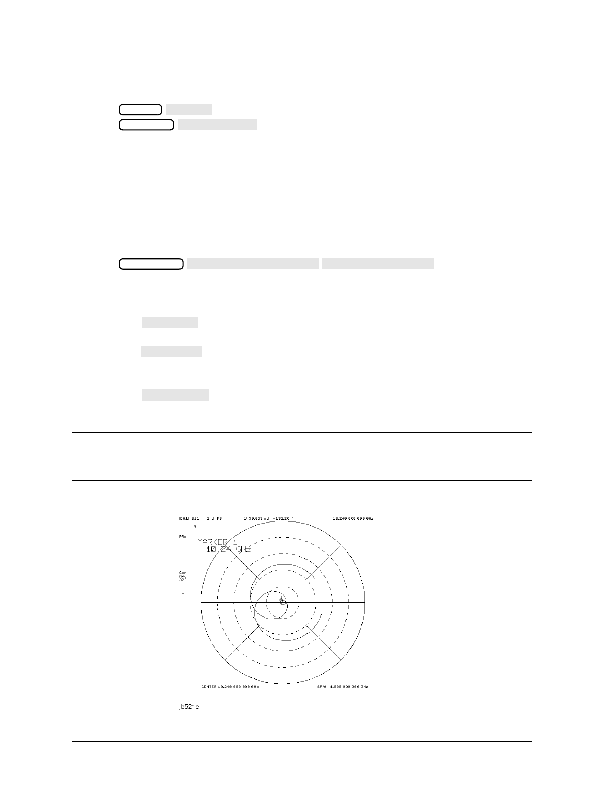
Figure 2-14 Example S
11
or Reflection Measurement Trace in Polar Format
Format
POLAR
Scale Ref
AUTO SCALE
Marker Fctn
MARKER MODE MENU
POLAR MKR MENU
LIN MKR
LOG MKR
Re/Im MKR