


Index
Index 1
Numerics
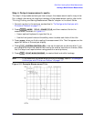
3 dB bandwidth
measuring
, 2-10
6 dB bandwidth
measuring
, 2-11
A
active channel keys
location
, 2-4
admittance
measuring
, 2-22
Agilent Technologies Sales and
Service Offices
, 2-26
analyzer configuration
, 1-9–1-19
attaching cabinet flanges with
front handles
, 1-19
attaching cabinet flanges
without front handles
, 1-18
attaching front handles
, 1-17
for bench top use
, 1-16
for rack mount use
, 1-16
option 1D5
, 1-10
standard
, 1-10
with printers or plotters
, 1-11
B
backing up EEPROM disk
, 1-26
bench top configuration
, 1-16
C
connectors
R channel
, 2-4
D
definitions
magnitude of reflection
coefficient
, 2-13
reflection coefficient
, 2-13
return loss (dB)
, 2-13
standing-wave-ratio (SWR)
,
2-13
disk drive location
, 2-3
disk eject button
, 2-3
display location
, 2-3
E
EEPROM backup disk
, 1-26
electrical and environmental
requirements
, 1-7
entry block location
, 2-4
F
front panel
, 1-5, 2-3
H
high stability frequency reference
configuration
, 1-10
I
impedance
measuring
, 2-21
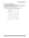
insertion loss
measuring
, 2-8
installation
, 1-2
instrument state function block
keys
, 2-4
L
line switch
, 2-3
location
active channel keys
, 2-4
disk drive
, 2-3
disk eject button
, 2-3
display
, 2-3
entry block
, 2-4
instrument state function block
keys
, 2-4
line switch
, 2-3
PORT 1
, 2-4
PORT 2
, 2-4
Preset key
, 2-4
R channel connectors
, 2-4
REFLECTION port
, 2-4
response function block keys
,
2-3
Return key
, 2-3
softkeys
, 2-3
stimulus function block keys
,
2-3
TRANSMISSION port
, 2-4
M
making measurements
, 2-1–2-22
measurement procedure
, 2-5
choosing measurement
parameters
, 2-5
measuring a device
, 2-5
outputting measurement
results
, 2-5
performing a measurement
calibration
, 2-5
measuring insertion loss with
marker functions
, 2-10
O
operation
, 1-20–1-25
installed options
, 1-21
operator’s check
, 1-23
self-test
, 1-22
testing reflection mode
, 1-25
testing transmission mode
, 1-24
operator’s check
, 1-23
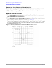
out-of-band rejection
measuring
, 2-11
P
parts list
parts received
, 1-4
passband flatness
measuring
, 2-12
passband ripple
measuring
, 2-12
plotter configuration
, 1-11
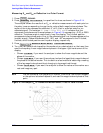
polar format
measuring
, 2-20
PORT 1
location
, 2-4
PORT 2
location
, 2-4
Preset key
location
, 2-4
printer configuration
, 1-11
problems, data entry
, 2-24
controls do not respond
, 2-24
parameters not accepted
, 2-24
problems, power-up
, 2-23–2-24
display does not light
, 2-23
display lights but fan does not
start
, 2-24
problems, RF output
, 2-24
no RF signal atfront panel port
,
2-24
R
R channel connectors
location
, 2-4
rack mount configuration
, 1-16
rear panel
, 1-6
reflection measurements
,
2-13–2-22
admittance
, 2-22
choosing measurement
parameters
, 2-14
impedance
, 2-21
measuring in polar format
, 2-20
measuring in smith chart
format
, 2-21
measuring reflection coefficient
,
2-18
measuring return loss
, 2-16
measuring standing wave ratio
(SWR)
, 2-19
measuring the device
, 2-16
outputting measurement
results
, 2-17