


Get Assistance, if You Need It 6
Agilent E6474A User’s Guide 115
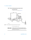
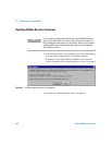
Preparing the software
1 Start the E6474A software.
2 Refer to “Identifying devices" on page 81, and perform the
procedure if you have not already done so.
3 Click Log > Start Live Mode.
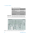
4 Open the Spectrum Analyzer view and maximize the view.
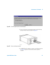
5 Set the measurement controls as follows:
Band: Downlink
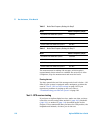
Frequency: See the tables on the next page.
Span: 300 kHz
Averaging: Running
Averages: 100
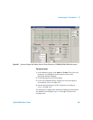
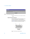
6 In the Markers group, click Add button then To Max and note
the Marker 1 frequency and level. The level and frequency are
displayed at the top-left corner of the Spectrum Analyzer
view.
7 In the Markers group, click Add to place a second marker on
the display.
8 Use the mouse to drag Marker 2 to the minimum level of the
trace. Note the Marker 2 frequency and level.
9 Calculate the average noise level of the downlink. Average
noise level = (Marker 1 level + Marker 2 level) / 2
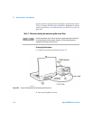
10 Select Uplink in the Band group. Frequency is displayed on
the Spectrum VFP.
11 Perform steps 7 through step 10 to determine the average
noise level of the uplink. Substitute the frequencies from
Table 6 on page 116 in step 6. Average noise level = (Marker 1
level + Marker 2 level) / 2
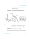
NOTE
The Agilent receiver requires a 30-minute warm-up period to meet the
guaranteed specifications. There is a three-minute delay after power-up or
re-configuration, before the internal temperature sensor is activated and
measurements are nominally correct.