


Connection Panels and LED Indicators B
Agilent E6474A User’s Guide 135
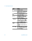
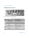
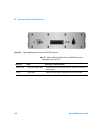
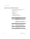
Table 9 E6473B hub rear panel descriptions (see Figure 61)
Power switch Left position = On
Center position = Off
Right position = Ignition Sense
Headset for Phone 2 Connect to headset
Phone 2 port Connect to phone interface cable
Reference Name Description or Cable Connection
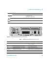
Figure 61 E6473B High Speed Direct Connect Hub rear panel
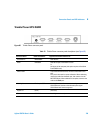
Reference Name Description or Cable Connection
Aux Out Power out connection Connect to power cable for second E645xx
Receiver (if equipped)
Rx Receive Data LED (Receiver or Aux ports) Flashes when data is received
Tx Transmit Data LED (Receiver or Aux ports) Flashes when data is transmitted
Receiver Receiver or Scanner Data port Connect to Receiver or scanner Data/Power cable
Aux Auxiliary Data Port Connect to GPS receiver or GPS/DR Navigation
Pwr In Power Input connection Connect to main power cable