


136 Agilent E6474A User’s Guide
B Connection Panels and LED Indicators
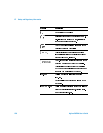
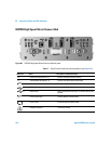
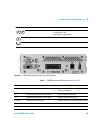
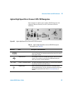
E645xx Receiver
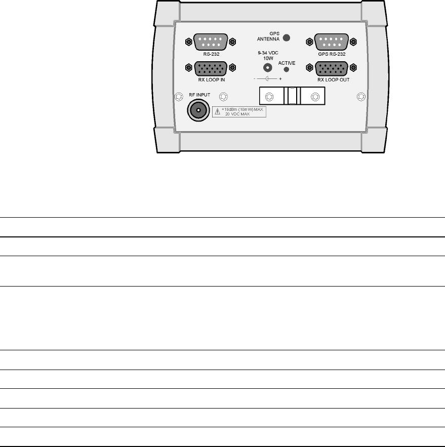
Table 10 E645xx Receiver connector panel descriptions (see Figure 62)
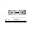
Figure 62 E645xx Receiver connector panel
Reference Name Description or Cable Connection
RS-232 Receiver data port Connect to receiver data/power cable
GPS Antenna GPS antenna connector Connect to GPS antenna, if equipped (included with E6455C; and
E6450B, E6452A, E6453A, and E6454A with GPS option)
GPS RS-232 External GPS data port For CDMA receivers, an optional 1 PPS cable may be connected to
this port, if the external navigator provides a 1 pulse per second
signal.
For E6455A, E6456A, and E645xC receivers, the cable for a wheel
pulse trigger may be connected to this port.
Rx Loop In Receive data loop input Connect to Rx Loop Out of second receiver (if equipped)
Rx Loop Out Receive data loop output Connect to Rx Loop In of second receiver (if equipped)
9-34 VDC Power input Connect to Receiver Data/Power cable
Active Active LED Glows when unit is powered on
RF Input RF antenna connector Connect to receiver’s RF antenna