


Connection Panels and LED Indicators B
Agilent E6474A User’s Guide 137
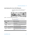
Agilent High Speed Direct Connect GPS/DR Navigation
This navigator is Agilent part number E6473B Options 030
(Magnetic Mount Antenna) and 031 (Permanent Mount
Antenna).
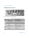
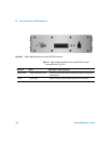
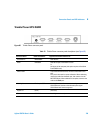
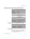
Table 11 Agilent High Speed Direct connect GPS/DR front panel
descriptions (see Figure 63)
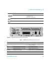
Figure 63 Agilent High Speed Direct Connect GPS/DR front panel
Reference Name Description or Cable Connection
Power switch Left-most position powers the unit on manually. The middle position
turns it off manually. The right-most position powers the unit on and off
by the ignition switch)
USB Connector The connector on the left is the USB Upstream port, which can connect
to the PC. The connector on the right is the USB Downstream port,
which can connect to another USB device.
Pwr / 1PPS Power / 1 Pulse Per Second The upper LED indicates that the power is on. The lower LED indicates
one pulse per second from the GPS receiver.
GYRO Position Allows unit to be positioned either vertically or horizontally without
affecting dead reckoning. The user indicates the position by moving the
Up pin to the appropriate position. Refer to “Gyro positioning" on
page 53.