


Use Your System 4
Agilent E6474A User’s Guide 75
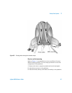
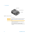
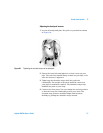
Figure 37 E6473B hub power switch positions
Agilent direct connect GPS/DR
If the ignition sense lead of the main power cable has been
connected to a +12 volt source, the navigator powers up when
the vehicle’s ignition is switched on and the power switch is in
either the Ignition (right) or Power (left) position. (For
installation instructions, Appendix D, “Permanent In-Vehicle
Hardware Installation,” starting on page 171.)
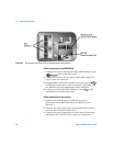
LEDs and display during power-up
The upper front panel LED indicates Power, and the lower LED
indicates 1PPS (Pulse Per Second). The information shown on
these two LEDs comes from the GPS Receiver. One use of the
1PPS would be to indicate that the GPS receiver is active. 1PPS
is also available at pin 9 of the rear panel RS-232 DB9 connector
and is enabled by software.
The Agilent direct connect GPS/DR status LCD displays
power-up and navigation status messages. The front panel LEDs
indicate CPU status, speed pulse status, and serial port activity.
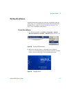
Determining GPS receiver status
You can determine whether the GPS Receiver is ready to
navigate by using the E6474A software as follows:
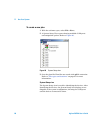
1 Start the E6474A software, and select Tools > Navigation to
display the Navigation dialog box.
2 Click the Live Mode button.
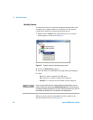
3 When the GPS Navigator is ready to track, the Satellites box
shows the number of satellites tracked, and the Navigation
OFF
Normal ON ON via ignition