


4 Agilent FrameScope 350 User’s Manual
1 Introducing the FrameScope 350
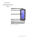
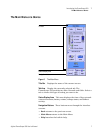
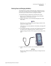
The FrameScope 350 at a Glance
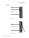
Controls
Color Touch Screen The FrameScope 350’s touch screen is the
main user interface. Test controls and results are shown here.
Simply press the screen with your finger or a stylus to navigate
through the menus and test controls.
Power Button Press the Power button briefly to switch the unit
on. To switch the unit off, do one of the following:
• Press Power twice.
• Press Power once, wait 5 seconds and the unit powers off.
• Press Power once and hit the Off button on the screen.
OK Button Press the OK button to activate the currently
selected item on the display. Use the OK button to confirm
edits, enter values, and execute selected features.
Scroll Button The scroll rocker button moves the highlight
cursor on the screen. Use this button to scroll through selected
items on the display.
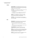
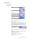
Ports
SmartProbe Port The SmartProbe test port on the top of the
FrameScope provides the network test interface. This port
accepts any of the Agilent SmartProbes such as:
• Channel SmartProbe for testing twisted pair using patch
cords.
• Link SmartProbe for testing twisted pair at network outlets.
• Fiber SmartProbe for testing optical fiber.
CompactFlash™ Slot This port on the bottom of the unit
accepts standard CompactFlash™ cards for data storage.
USB Ports The FrameScope provides two universal serial bus
(USB) interface ports to connect with PCs and peripherals. The
unit provides a USB Type A (Host) port and a USB Type B
(Hub) port. See “USB-A port” on page 227.
Serial Port The Serial port provides an 8-pin RS-232 interface
for connecting a PC. See “Serial port” on page 227.