


Introduction to the 34980A 1
34980A User’s Guide 3
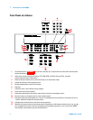
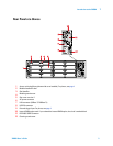
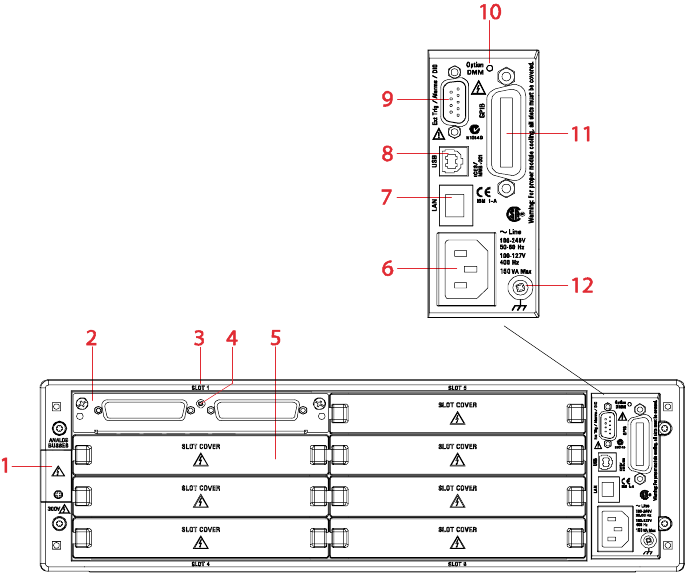
Rear Panel at a Glance
1
Access to Analog Buses (shown with cover installed). For pinout, see page 4.
2
Module installed in slot 1
3
Slot identifier
4
Module ground screw
5
Slot cover over slot 2
6
AC power connector
7
LAN connector (10Base T/100Base Tx)
8
USB 2.0 connector
9
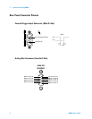
External trigger input. For pinout, see page 4.
10
Internal DMM option mark. If you ordered the internal DMM option, the circle is marked black.
11
IEEE 488.2 GPIB Connector
12
Chassis ground screw