


Chapter 1: Overview
18
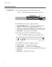
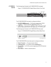
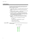
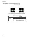
The stacking LED indications are described in the following table:
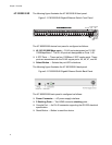
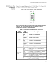
Mode LEDs You can select a particular status mode for a RJ-45 Port on either the AT-
8000GS/24 Gigabit Ethernet Switch or the AT-8000GS/48 Gigabit
Ethernet Switch by using the Mode Select switch button on the front panel.
(The AT-8000GS/24POE Gigabit Ethernet Switch does not have a Mode
select switch.)
The MODE LEDs indicate which mode is actively displayed on each
corresponding RJ-45 port Mode LED. For example, if the mode selected is
"COL", then the LED on each port indicates the collision status of that port.
See “RJ-45 Port LEDs on AT-8000GS/24 & AT-8000GS/48” on page 19
for the location of the RJ-45 MODE LED on each port.
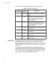
Table 4 Stacking LED Indications
LED
Description
LED
Indication
Description
All LEDs off The device is operating as a standalone
switch.
S1 Green The device is in stacking mode, and is
either the master or backup of the stack,
which is determined by the master
election algorithm.
S2 Green The device is master-enabled, and is
either the master or backup of the stack,
which is determined by the master
election algorithm.
S3 Green The device is operating as Stack Member
3 in the stack.
S4 Green The device is operating as Stack Member
4 in the stack.
S5 Green The device is operating as Stack Member
5 in the stack.
S6 Green The device is operating as Stack Member
6 in the stack.