


Overview
The AT-WDRPS-80 is a DC Redundant Power Supply (RPS) for the AT-WD1008
Multiplexer chassis. When installed, the unit shares the load of powering the
chassis with the standard power supply that comes pre-installed in the chassis. If a
power supply fails, the remaining unit provides all power to the system, thereby
preventing a network failure. The power supply is hot-swappable, meaning that
you can install it while the chassis is powered ON.
POWER
FAU LT
AT- W
DRPS-80
Related Documents
The Allied Telesyn web site at www.alliedtelesyn.com contains the most recent
documentation, software, and technical information for all of our products. For
details on the features and functions of your Allied Telesyn AT-WD1008 chassis and
modules, refer to the following manuals from our web site:
❑ AT-WD1008 Gigabit Ethernet Wavelength Division Multiplexer
Installation Guide
PN 613-50367-00
❑ AT-S47 Management Software User’s Guide
PN 613-50371-00
Package Contents
Make sure the following items are included in the shipping package. If any item is
missing or damaged, contact your Allied Telesyn sales representative for
assistance.
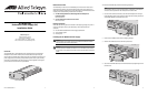
❑ One AT-WDRPS-80 Redundant Power Supply (DC) Module
❑ This installation guide
❑ Warranty card
Installing the AT-WDRPS-80 Power Supply
Caution
Before installing the module, refer to the AT-WD1008 Installation Guide for
electrical safety and emission information.
Caution
Do not install the AT-WDRPS-80 module in an AT-WD1008 chassis intended
for AC power. A DC powered chassis has two DC terminal blocks on the back
panel.
To install the AT-WDRPS-80, perform the following procedure:
Note
The AT-WDRPS-80 unit can be installed while the multiplexer is powered ON.
You do not need to power OFF the multiplexer to install the RPS.
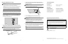
1. Loosen the two thumbscrews that secure the blank faceplate over the right-
hand redundant power supply expansion slot located on the front panel of the
AT-WD1008 Multiplexer and remove the cover.
2. Remove the AT-WDRPS-80 unit from its shipping package.
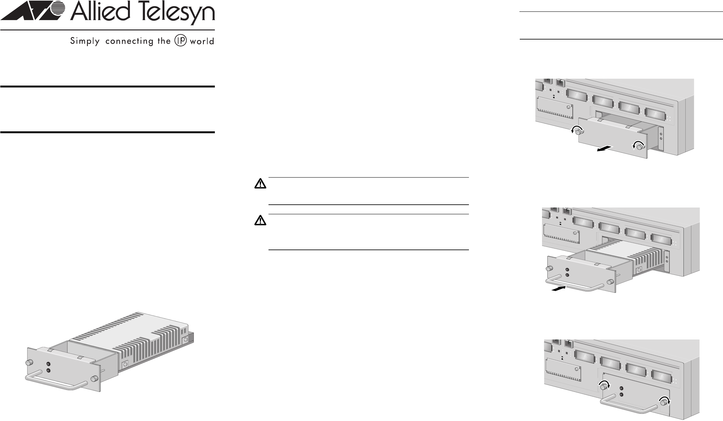
3. Slide the AT-WDRPS-80 unit into the RPS expansion slot.
4. Secure the AT-WDRPS-80 unit to the AT-WD1008 chassis by tightening the two
thumbscrews.
LNK TST
TX
RX
LNK TST
TX
RX
EAST
TX
SNMP MODULE
ST
T
X
R
X
RX
TX
CH 5
T
X
R
X
RX
TX
CH 6
T
X
R
X
RX
TX
CH 7
T
X
R
X
RX
TX
CH 8
T
X
R
X
F
A
N
A
F
A
N
B
POWER
SUPPLY B
WEST
EAST
NORMAL
LNK TST
L
N
K
T
S
T
T
X
R
X
L
N
K
T
S
T
T
X
R
X
EAST
T
X
SN
M
P M
ODULE
ST
TX
RX
R
X
T
X
CH
5
TX
RX
R
X
T
X
C
H 6
TX
RX
R
XT
X
CH 7
TX
RX
R
X
T
X
CH 8
TX
RX
FAN A
FAN B
POW
ER
SU
PPLY B
W
E
S
T
E
A
S
T
N
O
R
M
A
L
L
N
K
T
S
T
POWER
FAULT
AT-WDRPS-80
LNK TST
TX
RX
LNK TST
TX
RX
EAST
TX
SNMP MODULE
ST
TX
RX
RX
TX
CH 5
TX
R
X
RX
TX
CH 6
TX
RX
RX
TX
CH 7
TX
R
X
RX
TX
CH 8
TX
RX
FAN A
FAN
B
POWER
SUPPLY B
WE
ST
EAS
T
NORMAL
LNK TST
POWER
FAU LT
AT-WDRPS-80
AT-WDRPS-80
Redundant Power Supply (DC)
Installation Guide
Allied Telesyn, Inc.
960 Stewart Drive, Suite B
Sunnyvale, CA 94085 USA
Tel 1 (408) 730-0950 • Fax 1 (408) 736-0100
Visit our web site at: www.alliedtelesyn.com
PN 613-50406-00 Rev A
1 2 3