


Overview
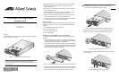
The AT-MCF2000AC module is an AC power supply unit for the AT-MCF2000
series of media converter chassis.
Figure 1. AT-MCF2000AC Power Supply Module
Note
For a list of available chassis models in the AT-MCF2000 media
converter product line, contact your Allied Telesis sales representative or
visit our web site.
1110-a
NORMAL
FAULT
STATUS
PSU
FAN
Review the following before you begin to install the module in the chassis:
❑ Refer to the chassis’ Installation Guide to verify that the module is
appropriate for the unit.
❑ For instructions on how to remove a power supply module, refer to the
chassis’s Installation Guide.
❑ The AT-MCF2000AC power supply module is hot-swappable. You can
install or replace the module while the chassis is powered on.
❑ Refer to the chassis’ Installation Guide for a list of safety precautions to
observe when installing the power supply module in the unit.
❑ The following procedure uses the AT-MCF2000 media converter chassis
for illustration purposes. Your chassis may be different.
Package Contents
Make sure the following items are included in the shipping package. If an item
is missing or damaged, contact your Allied Telesis sales representative for
assistance.
❑ One AT-MCF2000AC power supply module
❑ Four regional AC power cords
❑ One power cord retaining clip
❑ This Installation Guide
Installing the AT-MCF2000AC Power Supply Module
To install the AT-MCF2000AC power supply module, perform the following
procedure:
1. Remove the power supply module from the shipping package. Store the
packaging material in a safe location. You must use the original shipping
material if you need to return the unit to Allied Telesis.
2. Remove a blank panel from a power supply/fan module slot on the back
panel of the chassis by loosening the two captive screws of the panel with
a cross-head screwdriver. Refer to the chassis’ Installation Guide for the
location of the power supply/fan module slots.
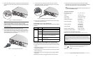
Figure 2. Removing the Blank Panel from a Power Supply/Fan Module Slot
3. Slide the power supply module into the slot as shown in Figure 3, until it is
flush with the back panel of the chassis. Light pressure may be needed to
seat the module on the connector on the back panel of the chassis.
AT-MCF2KPN
L2
AT-MCF2KPN
L3
1111-a
M
A
A
Caution
Do not force the module into place. Doing so may damage the
connector pins on the backplane inside the chassis.
Figure 3. Installing the AT-MCF2000AC Power Supply Module
4. Secure the power supply module to the chassis by tightening the two
captive screws using a cross-head screwdriver. Refer to Figure 4.
Figure 4. Securing the Power Supply Module
5. Locate the retaining brackets on either side of the AC power connector.
Refer to Figure 5.
Figure 5. Locating the Retaining Clip Brackets
A
T-MCF2KPN
L3
N
O
R
M
A
L
F
A
U
L
T
STATUS
P
S
U
F
A
N
1111-a
M
ANAG
A
1113-a
AT-
MCF2KPNL3
N
O
R
M
A
L
F
A
U
L
T
STATUS
P
S
U
F
A
N
M
A
AT-
MCF2KPNL3
NORMAL
FAU
LT
S
TA
TUS
PSU
FAN
M
A
Retaining Clip Brackets
AT-MCF2000AC Power Supply Module
Installation Guide
Allied Telesis, Inc.
www.alliedtelesis.com
613-000575 Rev A 1
*
613-000575 RevA*
2 3