


Overview
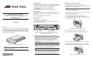
The AT-PWR14, shown in Figure 1, is an AC redundant power supply (RPS)
used with the AT-CV5000 chassis only. When installed, the module operates
in a standby mode. If the standard power supply fails or loses power, the AT-
PWR14 module changes from standby to active and provides all power to the
system to prevent a network failure.
Figure 1. AT-PWR14 Power Supply Module
Note
The power supply is hot-swappable. You can install it without powering
OFF the AT-CV5000 chassis.
POW
ER
FAULT
AT-PWR14
208
Related Documents
This installation guide is an abbreviated version of the installation procedure.
For details on the components, features, and functions of this product, refer to
the following documents on our web site, www.alliedtelesis.com:
❑ AT-CV5000 Media Converter Chassis Installation Guide
(PN 613-50580-00)
❑ AT-S70 Management Software User’s Guide (PN 613-50617-00)
Package Contents
Make sure the following items are included in the shipping package. If any
item is missing or damaged, contact your Allied Telesis sales representative
for assistance.
❑ One AT-PWR14 Redundant Power Supply (AC)
❑ This Installation Guide
❑ Warranty Card
Locations of the Power Supply Slots
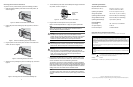
Figure 2 illustrates the locations of the two power supply modules at the rear
of an AT-CV5000 AC model chassis.
Figure 2. Locations of the Power Supply Slots on the Rear Panel of
an AT-CV5000 AC Model Chassis
Before installing a power supply, please note the following guidelines:
Note
The AT-CV5000 chassis comes with two slots designated for the power
supplies; however, it is shipped with one standard power supply
preinstalled and one empty slot for an optional power supply. The
redundant power supply can be ordered separately from your ATI sales
representative.
Note
Make sure that both power supplies (primary and redundant) are rated for
the same power ratings. For information on the power supply module,
refer to the documentation that is shipped with the module.
Note
The AT-PWR14 power supply can be installed in either one of the power
supply expansion slots while the converter chassis is powered ON. You
do not need to power OFF the chassis to install the power supply.
POWER
FAULT
AT-PWR14
AB
100-240VAC~
AT-CVFAN
A
100-240VAC~
AT-CVFAN
B
214
PS SLOT B - Redundant
PS SLOT A - Primary
Installing the AT-PWR14 Power Supply
To install the AT-PWR14, perform the following procedure:
1. Unpack the new AT-PWR14 module from its shipping container and store
the package material in a safe location.
Note
You must use the original shipping material if you need to return the
power supply module to Allied Telesis.
2. Select the power supply slot in the AT-CV5000 chassis where you want to
install the AT-PWR14 power supply.
3. Make sure that the power switch is in the OFF position.
4. Loosen the two captive screws that secure the blank slot cover
(AT-CV5PNL2) of the selected power supply slot, and remove the blank
slot cover, as shown in Figure 3.
Figure 3. Removing the Power Supply Slot Cover
5. Remove the AT-PWR14 module from its shipping package.
6. Slide the AT-PWR14 module into the RPS slot, as shown in Figure 4.
Figure 4. Inserting the AT-PWR14 Module into the Power Supply Slot
7. Secure the AT-PWR14 module to the AT-CV5000 chassis by using a
Phillips screwdriver to tighten the captive screws, as shown in Figure 5.
Figure 5. Securing the AT-PWR14 Module
211
A
1
0
0
-
2
4
0
V
A
C
~
AT-CVFAN
A
100-240VAC
~
W
AR
N
IN
G
T
h
i
s
u
n
i
t
m
i
g
h
t
h
a
v
e
m
o
r
e
t
h
a
n
o
n
e
p
o
w
e
r
i
n
p
u
t
.
T
o
r
e
d
u
c
e
t
h
e
r
i
s
k
o
f
e
l
e
c
t
r
i
c
s
h
o
c
k
,
d
i
s
c
o
n
n
e
c
t
a
l
l
p
o
w
e
r
i
n
p
u
t
s
b
e
f
o
r
e
s
e
r
v
i
c
i
n
g
u
n
i
t
.
209
A
1
0
0
-
2
4
0
V
A
C
~
POWER
FAU
LT
A
T-PW
R14
A
W
A
R
N
I
N
G
T
h
i
s
u
n
i
t
m
i
g
h
t
h
a
v
e
m
o
r
e
th
a
n
o
n
e
p
o
w
e
r
i
n
p
u
t
.
T
o
r
e
d
u
c
e
th
e
r
i
s
k
o
f
e
le
c
t
r
i
c
s
h
o
c
k
,
d
i
s
c
o
n
n
e
c
t
a
ll
p
o
w
e
r
i
n
p
u
t
s
b
e
f
o
r
e
s
e
r
v
i
c
i
n
g
u
n
i
t
.
212
A
1
0
0
-2
4
0
V
A
C
~
POWER
FAULT
AT-PWR14
A
AT-CVFAN
1
0
0
-
2
4
0
V
A
C
~
W
A
R
N
I
N
G
T
h
i
s
u
n
i
t
m
ig
h
t h
a
v
e
m
o
r
e
th
a
n
o
n
e
p
o
w
e
r
in
p
u
t.
T
o
r
e
d
u
c
e
t
h
e
r
i
s
k
o
f
e
le
c
t
r
ic
s
h
o
c
k
,
d
is
c
o
n
n
e
c
t
a
l
l
p
o
w
e
r
in
p
u
t
s
b
e
f
o
r
e
s
e
r
v
i
c
in
g
u
n
i
t
.
CONVERTEON™
Family
AT-PWR14 Redundant Power Supply (AC)
Installation Guide
Allied Telesis, Inc.
www.alliedtelesis.com
613-50585-00 Rev C
1
2 3
*613-50585-00 Rev C*