


Installation and User’s Guides
This document contains an abbreviated version of the installation instructions for the
AT-TQ3600 Wireless Access Point. For complete installation and management
instructions, refer to the AT-TQ3600 installation Guide and AT-TQ Wireless Access Point
Series User’s Guide on the Allied Telesis web site at www.alliedtelesis.com/support.
Safety and Electromagnetic Emissions Certificates
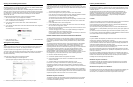
Installation Options
Table or desktop
Wall or ceiling
This quick installation guide explains how to install the device on a table or desktop. For
instructions on how to install the device on a wall of ceiling, refer to the AT-TQ3600
Wireless Access Point installation Guide.
Note:
The non-US model of this product has a country code setting that must be set during the
initial management session of the unit. The setting ensures that the unit operates in
compliance with the laws and regulations of your country or region.
The country code for the US model is preset and cannot be changed. Per FCC regulations,
the country code setting for all WiFi products marketed in the US must be fixed to US
operational channels only.
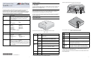
Physical Description
The AT-TQ3600 Wireless Access Point is shown in this figure.
The LEDs on the top panel of the access point are described in this table.
You may turn off the LEDs with the management software.
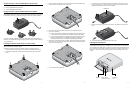
These two figures identify the components of the access point.
The components on the access point are described in this table.
You should review the safety precautions in the AT-TQ3600 Wireless Access Point
Installation Guide before installing the product.
The cable specifications for the LAN port are detailed in the AT-TQ3600 Wireless Access
Point Installation Guide.
Standard
Compliance
RoHs compliant
European Union RoHS (Directive 2011/65/EU of the European
Parliament and of the Council of 8 June 2011 on the restriction of
the use of certain hazardous substances in electrical and
electronic equipment.)
Certificates CE EAC
FCC/IC KC
RCM SRMC
Wi-Fi CERTIFIED
Electromagnetic
Compatibility (EMC)
EN 301 489-1 EN 301 489-17
EN 55022 EN 55024
EN 61000-3-2 EN 61000-3-3
EN 61000-4-2 EN 61000-4-3
EN 61000-4-4 EN 61000-4-5
EN 61000-4-6 EN 61000-4-11
AS/NZS CISPR 22
FCC 47 CFR Part 15, Subpart B
ICES-003
Medical (EMC) EN 60601-1-2
Radio Equipment EN 300 328 EN 301 893
AS/NZS 4268 RSS210
RSS-Gen RSS-102
FCC 47 CFR Part 15, FCC 47 CFR Part 15,
Subpart C Subpart E
FCC part 2
Safety EN 60950-1 IEC 60950-1
TUV-T UL 60950-1
UL 2043 (For AT-TQ3600-01 only)
Suitable for use in environmental air space in accordance with
Section 300-22(C) of the National Electrical Code, and Sections
2-128, 12-010(3), and 12-100 of the Canadian Electrical Code
Part 1, CSA C22.1.
Quick Installation Guide
AT-TQ3600
Wireless Access Point
*613-001862 Rev C*
613-001862 Rev. C
Table 1. LEDs
LED State Description
PWR Solid
Green
The unit is receiving DC power that is within the normal
operating range.
Off The power supply is not receiving power from either the
AC/DC power adapter or a PoE Ethernet switch.
SYS Amber The access point is loading its firmware.
Off The unit is operating normally.
10M and
100M
10M: On
100M: Off
The Ethernet port is operating at 10 Mbps.
10M: Off
100M: On
The Ethernet port is operating at 100 Mbps.
10M: On
100M: On
The Ethernet port is operating at 1000 Mbps.
2.4GHz Green The 2.4GHz radio is sending and receiving radio waves.
5GHz Green The 5GHz radio is sending and receiving radio waves.
PWR SYS 10M 100M 2.4GHz 5GHz
AT-TQ3600
3122
Table 2. Access Point Components
Component Description
1 Holes for anti-
theft devices
Refer to “Installing Anti-theft Devices”.
2 Console Port The Console Port is for manufacturing purposes only.
3 Reset Button The Reset button returns the parameter settings on the access
point to their default settings.
4 LAN Port The 10/100/1000Base-T LAN port connects the access point to
your wired network. It supports PoE. If you connect the port to an
Ethernet switch that supports PoE, you do not have to use the
power adapter to power the device.
5 DC Power
Connector
This connector is for the AT-TQ0091 AC/DC Power Adapter. You
may power the access point with PoE on the LAN port or the
power adapter. The power adapter must be ordered separately.
CONSOLE
RESET
3101
231
3121
4
5
1 2 3