Tel.: 1 (450) 444 2030 • Toll Free: 1-888-222-1560 • Fax: 1 (450) 444 2029 • Internet: www.kantech.com DN1776-0809
Copyright © 2008 Tyco International Ltd. and its Respective Companies. All Rights Reserved. • Specifications may change without notice.
Kantech and the Kantech logo are trademarks of Tyco International Ltd. and its Respective Companies.
KT-MOD-INP16
KT-400 Expansion Module 16-Zone Input with SPI Cable Install Sheet
1. Introduction
The KT-MOD-INP16 is an input module that adds up to 16 zones
to the KT-400 controller. The module supports daisy chaining;
you can interconnect up to 15 KT-MOD-INP16 modules for a total
of 240 external inputs per KT-400. Adding the 16 onboard inputs
of the KT-400 gives a total of 256 inputs per KT-400. Combining
input and output expansion modules gives the flexibility to
connect up to 256 inputs and 256 outputs.
Note 1: The KT-400 SPI port maximum current draw, when the
12V AUX terminals are not used, is 500 mA.
Note 2: External power supply (12 VDC, 2 Amps) is required
when the total current draw exceeds 500mA on the SPI Port.
2. Specifications
• Maximum Current Draw: up to 40 mA per module
• Supports single end-of-line (5600 ohm resistors) and
no end-of-line (DRY) zone loops
• Supports Normally Closed (NC) and Normally Open (NO)
contacts
• The C (Common) terminal is +12 VDC
• Input change with a debouncing of 500 ms (Slow) or
150 ms (Fast)
• Reports one condition per input: SECURE or ALARM
• Can be used for contact or elevator input
• Cannot be connected to output modules KT-MOD-REL8 and
KT-MOD-OUT16 through SPI OUT, only through its SPI EXP
expansion port
3. Installing the KT-MOD-INP16 Module
3.1. Unpacking
The KT-MOD-INP16 package includes the following parts:
• One (1) KT-MOD-INP16 module, 14 cm x 8 cm (5.7 in x 3.25
in)
• One (1) SPI cable with 1 SPI connector, 41 cm (16 in)
• Four (4) plastic standoffs
• Two (2) installation sheets, English and French
3.2. Mounting
The KT-MOD-INP16 can be installed inside a compatible cabinet
(KT-MOD-CAB or KT-400) or mounted in a dry and secure
location at less than 1 m (3 ft) from the KT-400.
1. Press the four (4) plastic standoffs through the mounting
holes of the cabinet,
2. Secure the cabinet to the wall in the desired location. Use
appropriate wall anchors when securing the cabinet to
drywall, plaster, concrete, brick or other surfaces.
3. Press the module into the plastic standoffs to secure the
module to the cabinet.
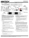
3.3. SPI Wiring
Perform the following steps to complete wiring:
Note 1: Before beginning to wire the unit, ensure that all power
(AC transformer and battery) is disconnected from the KT-400.
Note 2:
If you are combining input and output modules through
the SPI EXP expansion port of the KT-MOD-INP16, the input
module must be the 1
st
module connected to the KT-400 SPI
Port.
1. Connect the 6-pin SPI connector to the KT-400 SPI port or to
the SPI OUT of the previous KT-MOD-INP16 module.
2. Connect the six SPI wires (blue (BLU), white (WHT), green
(GRN), yellow (YEL), black (BLK) and red (RED)) to the SPI
IN (TB1) terminals.
3. You can use the SPI EXP of the 1
st
KT-MOD-INP16 to start a
group of output modules (KT-MOD-REL8 and KT-MOD-
OUT16 only).
4. Connect the 6-pin SPI connector from the SPI OUT to the
next KT-MOD-INP16 module.
5. Complete all zone wiring to the zone input terminals (Z1-Z16).
3.4. Check the power jumper JP5 position. Put it on EXT if you
need external power or INT if no external power is required.