


User's Guide 70
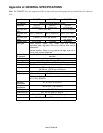
Appendix B: INTERFACE SPECIFICATIONS
This appendix presents the serial and parallel interface specifications. These specifications include pin assignments,
protocols and detailed information about how to properly interface your printer with your host or terminal.
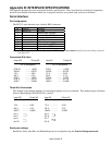
Serial Interface
Pin Configuration
The RS-232 serial interface uses a female, DB-9 conncetor.
Pin Direction Definition
1 Tied to in 6 Not used
2 In Receive Data (RxData)
3 Out Transmit Data (TxData)
4 - No connection
5 - Logic Ground
6 Tied to pin 1 Not used
7 Out Request to Send (RTS)
8 In Clear to Send (CTS)
9Out +5V
Note: Pin 9 is reserved for Keyboard Device Unit (KDU) only, do not connect this pin if you are using a general
host like a PC.
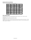
Connection With Host
Host 25S Printer 9P Host 9S Printer 9P
(PC or compatible) (PC or compatible)
DTR 20 ……… 1 DSR DTR 4 ……… 1 DSR
DSR 6 ……… 6 DTR DSR 6 ………6 DTR
TX 2 ……… 2 RX TX 3 ……… 2 RX
RX 3 ……… 3 TX RX 2 ………3 TX
CTS 5 ……… 7 RTS CTS 8 ……… 7 RTS
RTS 4 ……… 8 CTR RTS 7 ……… 8 CTS
GND 7 ……… 5 GND GND 5 ……… 5 GND
Three Wire Connection
This method is the simplest method of connecting the printer to a host or terminal. This method requires Software
Protocol Handshaking (XON/XOFF flow control).
Host 25S Printer 9P Host 9S Printer 9P
(PC or compatible) (PC or compatible)
TX 2 ……….. 2 RX TX 3 ……….. 2 RX
RX 3 ……….. 3 TX RX 2 ……….. 3 TX
GND 7 ……….. 5 GND GND 5 ……….. 5 GND
pin 4 pin 4
pin 5 Pin 6
pin 6 Pin 7
pin 20 Pin 8
Serial port settings
Baud Rate, Parity, Data Bits, and Handshaking may be configured using the Feature Management mode.