


Data Communications
20
Serial Port Specifications
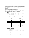
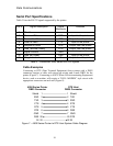
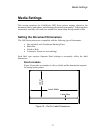
Table 3 lists the RS-232 signals supported by the printer.
Pin # Signal Description Signal
Mnemonic
Direction
1 Shield -- --
2 Received Data RXD Input to the printer
3 Transmitted Data TXD Output from the printer
4 Clear to Send CTS Input to the printer
5 Request to Send RTS Output from the printer
6 Data Terminal Ready DTR Output from the printer
7 Signal Ground GND --
20 Data Set Ready DSR Input to the printer
22 Ring Indicator RI Output from the printer
Table 3 - CodeWriter 4500 Series RS-232 Signals
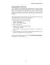
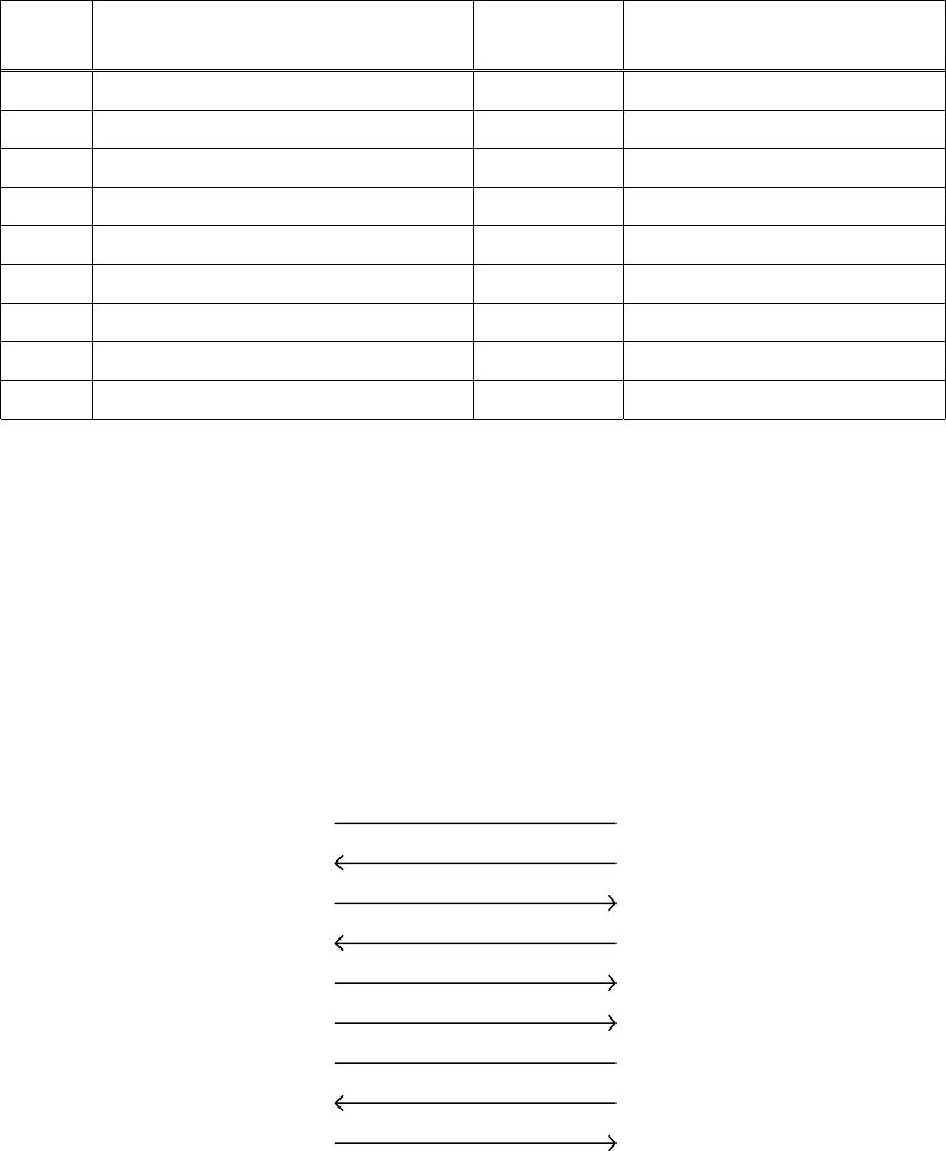
Cable Examples
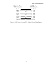
Connecting to DTE (Data Terminal Equipment) host systems with a DB25
connector requires a cable with pin-to-pin wiring and a male DB25 for the
printer (Figure 7). Connecting to a DCE (Data Circuit-terminating Equipment)
device, such as a modem, will require a “NULL-MODEM” style circuit with
appropriate connectors on each end (Figure 8).
Figure 7 – 4500 Series Printer to DTE Host System Cable Diagram
Shield 1
RXD 2
TXD 3
CTS 4
RTS 5
DTR 6
GND 7
DSR 20
RI 22
1 Shield
2 TXD
3 RXD
4 RTS
5 CTS
6 DSR
7 GND
20 DTR
22 RI
DTE Host
DB25 Connector
4500 Series Printer
DB25 Connector