


Installation Guide
MAX-CSE Video Encoder
MAX-CSE Video Encoder
This unit (FG2178-70) allows audio and video signals to be delivered in real-time
across any IP network for broadcast to a virtually limitless number of destinations –
classrooms, boardrooms, training facilities, retail store branches, and other
commercial settings.
The MAX-CSE provides real-time encoding of both analog audio or video content into
both MPEG-2 and MPEG-4 formats for delivery across these same IP networks
directly to either a MAX-CSD10 Decoder, Modero VG-Series Touch Panel, or
computer (for immediate playback via a third-party streaming MPEG player).
The rear Ethernet port provides both 10/100 Ethernet connectivity and IEEE 802.3af
Power-over-Ethernet (PoE) which enables DC power to be supplied to this device over
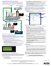
the unused pairs of wires on the connected Ethernet cable. FIG. 1 shows the front and
rear views.
Note: This unit can be mounted onto either a flat surface or into an equipment rack by
first removing the front screws and then attaching it to an AC-RK.
Product Specifications
Wiring Installation Procedures
The wiring parameters for the PWR, Serial, and Ethernet ports are described in detail
within the following sections.
Wiring the power connector
Use an external power supply, described in the Specifications table, to provide power
to the MAX-CSE through the rear 2-pin 3.5 mm mini-Phoenix connector (FIG. 1). The
incoming PWR and GND wires from the power supply must be connected to the
corresponding locations within the PWR connector.
Power-over-Ethernet connection
Caution: When using PoE, you must FIRST ground the unit to provide ESD
protection. Install a single wire into the (-) GND side of the rear green 2-pin PWR
connector, and then connect the terminal-end of this wire to a grounded source.
It is recommended that the length of this wire NOT exceed 6 ft. (1.83 m).
Any 802.3af-compliant PoE switch (such as the NXA-ENET24 PoE) can automatically
detect the 802.3af-compliant MAX device by its authenticated PoE signature and
sense its required load before applying power to the PoE Ethernet port.
Note: PoE connections work with all existing Category (CAT) 3, 4, 5, 5e or 6 network
cabling (including patch cables and patch-panels, outlets, and other connecting
hardware) without requiring modification.
Reading the Ethernet LEDs
The MAX-CSE uses a standard CAT5 Ethernet cable to provide 10/100 network
connectivity to the network (FIG. 2). LEDs indicate communication activity, connection
status, speeds, and mode information.
FIG. 1 MAX-CSE Video Encoder (front and rear views)
MAX-CSE Specifications
Dimensions (HWD): 1.58" x 5.54" x 6.95" (4.01 cm x 14.07 cm x 17.65 cm)
Power Requirements: • 500mA @ 12VDC (6W)
• Optional 12VDC power input overrides PoE when used.
• Power requirements are usage dependant.
• Power Over Ethernet (PoE) is available.
• This product is intended to be supplied by a Listed external power
supply rated from 10 to 18 VDC, minimum 500 mA or equivalent.
Weight: • 2.02 lbs (0.92 kg)
Enclosure: • Metal with black matte finish
Certifications: • FCC Part 15 Class B, CE, and UL listed
Video Inputs: • Composite Video (via BNC).
• S-Video (via female S-Video connector)
Audio Inputs: • Analog Stereo RCA connectors
• Microphone (1/8” stereo)
Supported Resolutions: • NTSC (480i)
•PAL (576i)
Supported Video
Codecs:
• MPEG-2 (2 Mbps - 6 Mbps)
• MPEG-4 (500Kbps - 3 Mbps)
• Adjustable Bit Rate: up to 6 Mbps
Supported Audio
Codecs:
• MPEG Audio Level 2 (MP2)
• MPEG Audio Level 3 (MP3)
Front Panel
Components:
• ID Pushbutton: Used to set the NetLinx ID (Device only)
assignment, and reset the unit to factory defaults.
• Status LED: Green LED blinks to indicate both the system and
communication status with the target Master.
• LCD Display: Provides system information such as the currently
used IP Address.
• IR Receiver: Receives 38KHz AMX IR codes.
Rear Panel Connectors: • COMPOSITE IN: BNC connector (female) supports Composite
Video Input (NTSC/PAL).
• 12VDC PWR: 2-pin 3.5mm mini-Phoenix (male) captive-wire
connector from an optional 12 VDC power supply (overrides PoE).
• S-VIDEO IN: Mini-Din4 port for composite S-Video input.
Ethernet
12 VDC
(front)
(rear)
Composite IN
Ethernet Speed and
S-Video IN
IR/Serial port
Analog stereo audio
Microphone
ID button
Status LED
LCD Display IR Receiver
Power
Link Activity LEDs
RS232/422/485
port
Input/Output
port
(BNC)
MAX-CSE Specifications (Cont.)
Rear Panel Connectors
(Cont.):
• ETHERNET 10/100: RJ-45 port provides 10/100 Mbps network
communication and PoE. LEDs show communication activity,
connection status, speeds, and mode information (FIG. 2).
• AUDIO R/L: Two RCA connectors support line-level stereo input for
analog stereo signals.
• RS-232/422/485: 9-pin (DB9) port supports
RS-232/RS-422/RS-485 data output including:
- 300, 600, 1,200, 2,400, 4,800, 9,600, 19,200, 38,400, and
115,200 Baud rates
- 8 or 9 Data bits
- 1 or 2 Stop bits
- Even, Odd, Mark, Space, and None parity settings
- CTS and RTS handshaking
- XON/XOFF handshaking
• MIC: 1/8” mini-stereo input jack.
• IR/Serial: 2-pin 3.5mm mini-Phoenix (male) captive-wire connector
provides IR/Serial control output by generating IR with the use of an
IR emitter (while in IR mode). This port supports high-frequency
carriers of up to 1.142 MHz and can also generate IR with no carrier
frequency.
• I/O: Two digital 4-channel binary I/O ports for contact closure
(accepts a 4-pin 3.5mm mini-Phoenix captive-wire connector).
Each input is capable of voltage sensing. Input format is software
selectable with interactive power sensing for IR ports.
Operating/Storage
Environment:
• Operating Temperature: 0° to 45° C (32° to 113° F)
• Storage Temperature: -30º to 70º C (-22º to 158° F)
• Operating Relative Humidity: 5% to 85% (non-condensing)
• Operation intended for indoor use only.
Included
Accessories:
• 2-pin 3.5 mm mini-Phoenix female PWR connector (41-5025)
• 4-pin 3.5 mm mini-Phoenix female I/O connector (41-5047)
• BNC to RCA Adapter (41-1074)
• CC-NIRC IR Emitter cable
• MAX-CSE Quick Start Guide
Other AMX Equipment: • AC-RK Accessory Rack Kit (FG515)
• CSB Cable Support Bracket (FG517)
• PMB Pole Mount Bracket (FG531)
• STS, Serial To Screw Terminal (FG959)
• Surface Mount Bracket Accessory (FG525)
FIG. 2 Ethernet LEDs
SPD
L/A
ETHERNET 10/100
SPD - Speed LED lights (yellow) when
and turns Off when the speed
is 10 Mbps.
the connection speed is 100 Mbps
L/A - Link/Activity LED lights
(green) when the Ethernet
cables are connected and terminated
correctly. Blinks when receiving
Ethernet data packets.