


Installation Guide
NI-2100 NetLinx
®
Integrated Controller
Overview
The NI-2100 (FG2105-04), satisfies the control and automation features common in a
single room, which may include the integration of a limited number of DVD players,
projectors, lighting, thermostats and other electronic equipment. For smaller business
and home applications, the NI-2100 includes just the right mix of ports and features.
The NI-2100 can be upgraded to provide one ICSHub and two ICSNet ports by either
installing the optional ICSNet daughter card (FG2105-10) or purchasing this upgrade
as an included feature of the NI-2100 Kit (FG2105-14).
ATTENTION!
Verify you are using the latest NI firmware for the on-board Master. Verify you are
using the latest version of NetLinx Studio (available for download from
www.amx.com).
Specifications
Connections and Wiring
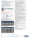
FIG. 2 shows the layout of the connectors and components on the rear of the NI-2100
NetLinx Integrated Controller.
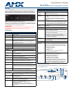
FIG. 1
NI-2100 NetLinx Integrated Controller (front view)
NI-2100 Specifications
Dimensions (HWD): • 3.47" x 17.00" x 3.47" (8.81 cm x 43.18 cm x 8.82 cm)
• 2 rack units high
Power Requirement: 700 mA @ 12 VDC
Memory: • 64 MB SDRAM
• 1 MB Non-volatile (NV) SRAM
Compact Flash: 128 MB or more - Upgradeable (see Other AMX Equipment)
Note: AMX may increase Flash size at any time in response to
market availability (refer to product’s online catalog page for current
Compact Flash size provided).
Weight: 4.50 lbs (2.04 kg)
Enclosure: Metal with black matte finish
Certifications: FCC Part 15 Class B, CE, and IEC 60950
Front Panel LEDs:
• LINK/ACT: Green LED blinks when the Ethernet cables are connected and
terminated correctly. Also blinks when receiving Ethernet data
packets.
• Status: Green LED blinks to indicate that the system is programmed and
communicating properly.
• Output: Red LED blinks when the Controller transmits data, sets channels
On and Off, sends data strings, etc.
• Input: Yellow LED blinks when the Controller receives data from button
pushes, strings, commands, channel levels, etc.
• RS-232/422/485: 3 sets of red and yellow LEDs light to indicate that DB9 Ports 1 - 3
are transmitting or receiving RS-232, 422, or 485 data.
• Relay: 4 red LEDs light to indicate the relay channels 1 - 4 are active
(closed). These LEDs reflect the state of the relay on Port 4.
• IR/Serial: 4 red LEDs light to indicate the IR/Serial channels 1 - 4 are
transmitting control data on Ports 5 - 8. LED indictor for each IR port
remains lit for the length of time that IR/Serial data is being gener-
ated.
• I/O: 4 yellow LEDs light when the I/O channels 1 - 4 are active. The LED
for each I/O port reflects the state of that particular port.
Rear Panel Components:
• RS-232/422/485
(Ports 1 - 3):
3 RS-232/422/485 control ports using DB9 (male) connectors with
XON/XOFF (transmit on/transmit off), CTS/RTS (clear to send/ready
to send), and 300-115,200 baud.
• ICSNet: 2 RJ-45 connectors for ICSNet interface (provided by optional
ICSNet daughter card).
• ICSHub Out: RJ-45 connector provides data to a Hub connected to the Controller
(provided by optional ICSNet daughter card).
• Relay (Port 4): • Four-channel single-pole single-throw relay ports
• Each relay is independently controlled.
• Supports up to 4 independent external relay devices
• Channel range = 1-4
• Each relay can switch up to 24 VDC or 28 VAC @ 1 A
• 8-pin 3.5 mm mini-Phoenix (female) connector provides relay
termination
NI-2100 Specifications (Cont.)
Rear Panel Components (Cont.):
• Digital I/O
(Port 9):
4-channel binary I/O port for contact closure with each input being
capable of voltage sensing. Input format is software selectable with
interactive power sensing for IR ports.
•IR/Serial
(Ports 5 - 8):
4 IR/Serial control ports support high-frequency carriers of up to
1.142 MHz with each output being capable of two electrical formats:
IR or Serial.
• 4 IR/Serial data signals can be generated simultaneously.
• IR ports support data mode (at limited baud rates and wiring
distances).
• Program Port: RS-232 DB9 connector (male) can be connected to a DB9 port on a
PC. This connector can be used with serial and NetLinx program-
ming commands, as well as other DB9 capable devices, to both
upload/download information from the NetLinx Studio program.
• Configuration DIP
Switch:
Sets the communication parameters for the Program port (see Baud
Rate Settings).
• ID Pushbutton: Sets the NetLinx ID (Device only) assignment for the device.
• Ethernet Port: RJ-45 connector provides TCP/IP communication. This is an Auto
MDI/MDI-X enabled port, which allows you to use either straight-
through or crossover Ethernet cables.
The Ethernet Port LEDs show communication activity, connection
status, speeds, and mode information:
• SPD (speed) - Yellow LED lights On when the connection speed is
100 Mbps and turns Off when the speed is 10 Mbps.
• L/A (link/activity) - Green LED lights On when the Ethernet cables
are connected and terminated correctly, and blinks when
receiving Ethernet data packets.
• AxLink Port: 4-pin 3.5 mm mini-Phoenix (male) connector that provides data and
power to external control devices. Green AXlink LED indicates the
state of the AXlink port.
• Power Port: 2-pin 3.5 mm mini-Phoenix (male) connector.
Included
Accessories:
• 2-pin 3.5 mm mini-Phoenix (female) PWR connector (41-5025)
• 4-pin 3.5 mm mini-Phoenix (female) AXlink connector (41-5047)
• 6-pin 3.5 mm mini-Phoenix female I/O connector (41-5063)
• 8-pin 3.5 mm mini-Phoenix female Relay connector (41-5083)
• Installation Kit (KA2105-01):
- 8-pin Relay Common Strip
- 4 rack mount screws
- 4 washers
• 2 CC-NIRC NetLinx IR Emitter Cables (FG10-000-11)
• 2 removable rack ears (62-2105-07)
Other AMX
Equipment:
• 2-pin 3.5 mm mini-Phoenix male connector (41-5026)
• CC-COM Programming Port Cable (FG10-727)
• CC-NSER IR/Serial cable (FG10-007-10)
• ICSNet daughter card (FG2105-10)
• NCK, NetLinx Connector Kit (FG2902)
• STS, Serial To Screw Terminal (FG959)
• Upgrade Compact Flash (factory programmed with firmware):
NXA-CF2NI256M - 256 MB compact flash card (FG2116-47)
NXA-CF2NI512M - 512 MB compact flash card (FG2116-48)
NXA-CF2NI1G - 1 GB compact flash card (FG2116-49)
FIG. 2 NI-2100 rear connectors and components
AXlink Port/LED
Relays
RS-232/422/485 (Ports 1-3)
I/O
IR/Serial
Program port DIP switch
ID Pushbutton
Ethernet
PWR
ICSNet cover plate
(Port 4) (Port 9)
(Ports 5-8)