


Installation Guide
NI-3101-SIG Signature Series NetLinx
®
Integrated Controller
Overview
The NI-3101-SIG Signature Series NetLinx Integrated Controller (FG2105-08)
satisfies the control and automation features common in a larger area or multiple
rooms, which may include the integration of a larger number of devices including VCR
and DVD players, projectors, lighting, thermostats and other electronic equipment. In
technology-driven environments, this solution allows for the future addition of more
devices and control capabilities.
The NI-3101-SIG features an easy-to-install form factor that mounts into 1 unit of rack
space and provides extended rack depth to simplify rear connections. Its sleek, gloss
black faceplate complements the Tango Distributed Audio line and Metreau Keypads.
ATTENTION!
Verify you are using the latest NI firmware for the on-board Master. Verify you are
using the latest version of NetLinx Studio (available for download from
www.amx.com).
Specifications
Connections and Wiring
FIG. 2 shows the layout of the connectors and components on the rear of the
NI-3101-SIG
Wiring a power connection
Use a 12 VDC-compliant power supply to provide power to the Controller via the rear
2-pin 3.5 mm mini-Phoenix connector. Use the power requirements information listed
in the Specifications table to determine the power draw.
The incoming PWR and GND cable from the PSN power supply must be connected to
their corresponding locations within the PWR connector.
• This unit should only have one source of incoming power.
• Using more than one source of power to the Controller can result in damage to
the internal components and a possible burn out.
• Apply power to the unit only after installation is complete.
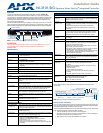
FIG. 1 NI-3101-SIG NetLinx Integrated Controller (front view)
NI-3101-SIG Specifications
Dimensions (HWD): • 2" x 17" x 10" (5.1 cm x 43.2 cm x 26.35 cm)
• 1 RU (rack unit) high
Power Requirement: 900 mA @ 12 VDC
Memory: • 64 MB SDRAM
• 1 MB Non-volatile (NV) SRAM
Compact Flash: • 128 MB or more
• AMX may increase Flash size at any time in response to market
availability
Weight: 6.95 lbs (3.15 kg)
Enclosure: Metal with black matte finish
Certifications: FCC Part 15 Class B, CE, and IEC 60950
Front Panel LEDs:
• Power: Blue LED bar lights when powered up.
• Link/Active: Blue LED blinks when the Ethernet cables are connected and
terminated correctly. Also blinks when receiving Ethernet data
packets.
• Status: Blue LED blinks to indicate that the system is programmed and
communicating properly.
• Input/Output: White LED blinks when the Controller transmits data, sets channels
On/Off, sends data strings, etc. Also blinks when it receives data
from button pushes, strings, commands, channel levels, etc.
• RS-232/422/485: 6 sets of blue and white LEDs light to indicate the rear DB9 Ports 1 -
6 are transmitting or receiving RS-232, 422, or 485 data.
• Relay: 8 blue LEDs light to indicate the rear relay channels 1 - 8 are active
(closed).
• IR/Serial: 8 blue LEDs light to indicate the rear IR/Serial channels 1 - 8 are
transmitting control data on Ports 9 - 16.
• I/O: 8 white LEDs light when the rear I/O channels 1-8 are active.
Rear Panel Components:
• RS-232/422/485
(Ports 1 - 6):
6 RS-232/422/485 control ports using DB9 (male) connectors with
XON/XOFF (transmit on/transmit off), CTS/RTS (clear to send/ready
to send), and 300-115,200 baud.
• ICSNet: 2 RJ-45 connectors for ICSNet interface (provided by optional
ICSNet daughter card).
• ICSHub Out: RJ-45 connector provides data to a Hub connected to the Controller
(provided by optional ICSNet daughter card).
• Relay (Port 8): • Eight-channel single-pole single-throw relay ports
• Each relay is independently controlled.
• Supports up to 8 independent external relay devices
• Channel range = 1-8
• Each relay can switch up to 24 VDC or 28 VAC @ 1 A
• Two 8-pin 3.5 mm mini-Phoenix (female) connectors provide relay
• termination
Power indicator
Link/Active LED
Status LED
Input/Output LED
RS-232/422/485 LEDs
Relay LEDs
I/O LEDs
IR/Serial LEDs
NI-3101-SIG Specifications (Cont.)
Rear Panel Components (Cont.):
• Digital I/O
(Port 17):
8-channel binary I/O port for contact closure with each input being
capable of voltage sensing. Input format is software selectable with
interactive power sensing for IR ports.
•IR/Serial
(Ports 9 - 16):
8 IR/Serial control ports support high-frequency carriers of up to
1.142 MHz with each output being capable of two electrical formats:
IR or Serial.
• 8 IR/Serial data signals can be generated simultaneously.
• IR ports support data mode (at limited baud rates and wiring
distances).
• Program Port: RS-232 DB9 connector (male) can be connected to a DB9 port on a
PC. This connector can be used with serial and NetLinx program-
ming commands, as well as other DB9 capable devices, to both
upload/download information from the NetLinx Studio program.
• Configuration DIP
Switch:
Sets the communication parameters for the Program port (see Baud
Rate Settings).
• ID Pushbutton: Sets the NetLinx ID (Device only) assignment for the device.
• Ethernet Port: RJ-45 connector provides TCP/IP communication. This is an Auto
MDI/MDI-X enabled port, which allows you to use either straight-
through or crossover Ethernet cables.
The Ethernet Port LEDs show communication activity, connection
status, speeds, and mode information:
• SPD (speed) - Yellow LED lights On when the connection speed is
100 Mbps and turns Off when the speed is 10 Mbps.
• L/A (link/activity) - Green LED lights On when the Ethernet cables
are connected and terminated correctly, and blinks when
receiving Ethernet data packets.
• AxLink Port: 4-pin 3.5 mm mini-Phoenix (male) connector that provides data and
power to external control devices. Green AXlink LED indicates the
state of the AXlink port.
• Power Port: 2-pin 3.5 mm mini-Phoenix (male) connector.
Included
Accessories:
• 2-pin 3.5 mm mini-Phoenix (female) PWR connector (41-5025)
• 4-pin 3.5 mm mini-Phoenix (female) AXlink connector
• (41-5047)
• 10-pin 3.5 mm mini-Phoenix (female) I/O connector (41-5107)
• Installation Kit (KA2105-02):
- 2 rack mount ears
- 4 #8-32 Phillips flat head screws
• Two 8-pin 3.5 mm mini-Phoenix (female) Relay connectors
(41-5083)
• 2 CC-NIRC NetLinx IR Emitter Cables (FG10-000-11)
Other AMX
Equipment:
• 2-pin 3.5 mm mini-Phoenix male connector (41-5026)
• CC-NSER IR/Serial cables (FG10-007-10)
• NCK, NetLinx Connector Kit (FG2902)
• USB A to B cable (FG10-2105)
FIG. 2 NI-3101-SIG rear connectors and components
AXlink Port/LED
Relays I/O IR/Serial
USB Program port
Configuration DIP switch
ID Pushbutton
Ethernet
PWR
(Port 8) (Port 17) (Ports 9-16)
RS-232/422/485
(Ports 1-6)