


Installation Guide
NXA-ENET24 PoE Fast Ethernet Switch
For more detailed installation, configuration, programming, and operating instructions,
refer to the NXA-ENET24 Hardware Installation and Software Management Guides
available on-line at www.amx.com.
Overview
The NXA-ENET24 PoE Fast Ethernet switch is specifically designed to protect the
video streams coming from AMX’s MAX units to the Audio Video Modules (AVM).
Standard switches will reduce bandwidth from all applications when there is heavy
data traffic passing through the switch. For streaming audio and video applications this
will cause skipping and jitter in the audio and video feeds. This is unacceptable for
AMX’s applications. As a result, AMX has designed the NXA-ENET24 PoE to protect
the A/V streams when heavy data traffic occurs. Bandwidth is reduced from other
applications such as file transfer, e-mail and web surfing only when heavy data traffic
events occur.
The NXA-ENET24 PoE also provides a full range of features for Layer 2 switching. It
includes a management agent that allows you to configure the features listed in the
products manual. The default configuration can be used for most of the features
provided by this switch. However, there are many options that you could configure to
maximize the switch’s performance for your particular network environment.
The NXA-ENET24 PoE’s 24 10/100 Mbps ports support the IEEE 802.3af Power-over-
Ethernet (PoE) that enables DC power to be supplied to attached devices over the
unused pairs of wires in the connecting Ethernet cable.
Description of Hardware
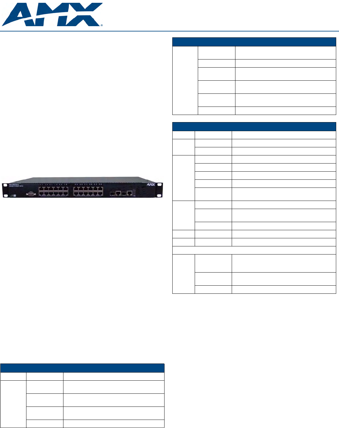
The NXA-ENET24 PoE Fast Ethernet switch measures 17.32 x 16.14 x 1.69 inches
(44.0 x 41.0 x 4.3 cm). (See FIG. 1)
10/100BASE-T Ports
The switch base unit contains 24 10BASE-T/100BASE-TX RJ-45 ports. All ports
support automatic MDI/MDI-X operation, so you can use straight-through cables for all
network connections to PCs or servers, or to other switches or hubs.
Each of these ports support auto-negotiation, so the optimum transmission mode (half
or full duplex), and data rate (10 or 100 Mbps) can be selected automatically. If a
device connected to one of these ports does not support auto-negotiation, the
communication mode of that port can be configured manually.
Each port also supports IEEE 802.3x auto-negotiation of flow control, so the switch
can automatically prevent port buffers from becoming saturated.
1000BASE-T/SFP Ports
These are combination Gigabit RJ-45 ports with alternate Small Form Factor
Pluggable (SFP) transceiver slots. If an SFP transceiver (purchased separately) is
installed in a slot and has a valid link on the port, the associated RJ-45 port is disabled.
The 1000BASE-T RJ-45 ports support automatic MDI/MDI-X operation, so you can
use straight-through cables for all network connections to PCs or servers, or to other
switches or hubs.
The 1000BASE-T RJ-45 ports do not support PoE capability.
Port and System Status LEDs
The LEDs, which are located on the front panel for easy viewing, are described in the
following tables.
The port status LEDs have two display modes; Link and PoE. The Link mode displays
the link status and network activity on each port. The PoE mode displays the PoE
power status on each port. Use the Mode Link/PoE button on the front panel to toggle
between the two display modes. The current mode is indicated by the Link/Act and
PoE system LEDs.
Stack Master Button
The Stack Master button enables one switch in the stack to be selected as the master.
Seven other switches can be stacked together and they should be placed in "Slave"
mode. When operating in a stand-alone configuration the switch should be in "Master"
mode.
Mode PoE/Link Button
The Mode PoE/Link button is located on the front panel.
The Mode PoE/Link button is used to toggle between the two port status LED display
modes. Pressing this button changes from one display mode to the other. The default
display mode is Link/Act mode.
Power Supply Receptacle
The standard power receptacle is for the AC power cord. It is located on the rear panel
of the switch.
MAX A/V Network
The switch is an excellent choice for mixed AMX equipment such as PoE enabled
NXA-WAP 200 G wireless access points, and non-PoE devices such as AVMs,
Breakout Boxes and MAX. You can easily build on this basic configuration, adding
direct full-duplex connections to AVMs, Breakout Boxes and WAPs. When the time
comes for further expansion, just connect to another hub or switch via one of the
switch’s Fast Ethernet or Gigabit Ethernet ports.
The switch automatically identifies the devices requirements, i.e., power for the
WAP200G and network priority for MAX streams to the AVMs so no configuration is
required by the installer.
FIG. 1 The NXA-ENET24 PoE Fast Ethernet switch
Port Status LEDs
LED Condition Status
1~24
(Link/Act
Mode)
On/Flashing
Green
Port has established a valid 100 Mbps network
connection. Flashing indicates activity.
On/Flashing
Amber
Port has established a valid 10 Mbps network con-
nection. Flashing indicates activity.
Alternate Green/
Amber
Port has been disabled by the administrator.
Off There is no valid link on the port.
Port Status LEDs (Cont.)
1~24
(PoE
Mode)
On Green Powered device is connected, but not drawing
power.
Flashing Green Powered device is receiving power.
Flashing Amber Port has detected a power overload or short circuit
and shut down the port’s power.
On Amber The power budget for the switch has been
exceeded and the port's power shut down.
Alternate Green/
Amber
Port has been disabled by the administrator.
Off No powered device is connected to the port.
System Status LEDs
LED Condition Status
PWR On Green Unit’s internal power supply is operating normally.
Off Unit has no power connected.
Diag On Green System diagnostic test successfully completed.
Flashing Green System diagnostic test is in progress.
On Amber System diagnostic test has detected a fault.
Flashing Amber Cannot receive packet from stacking port.
Alternate Green/
Amber
Fan has failed or the unit has over-heated.
Stacking On Green This switch is acting as the master unit in the stack.
Flashing Green Initial state of stacking configuration to determine
whether the switch will act as a master or slave unit.
On Amber This switch is acting as a slave unit in the stack.
Link/Act On Green LED display mode is Link/Act.
PoE On Green LED display mode is PoE.
Combination Ports
25-26
(Link/
Activity)
On/Flashing
Amber
Port has established a valid 10/100 Mbps network
connection.
Flashing indicates activity.
On/Flashing
Green
Port has established a valid 1000 Mbps network
connection. Flashing indicates activity.
Off There is no valid link on the port.