


Installation Guide
NXC-VAI4 Voltage Output/Analog Input Card
NetLinx Control Cards and NetModules
NetLinx Control Cards can be installed in either the NXF CardFrame, NI-4000, or
NetModules. This document provides basic specifications and wiring information for
the NetLinx Control cards. For detailed information on the cards, refer to the NetLinx
CardFrame, Control Cards, and NetModules Instruction Manual available on-line via
www.amx.com.
NXC-VAI4 Analog Voltage Control Card
The NXC-VAI4 Analog Voltage Control Card (FG2025) provides 4 independent
analog-to-digital inputs and four independent digital-to-analog outputs, which are
controllable over the ICSP network. Each port can be configured for a variety of DC
input and output signals. The NXC-VAI4 incorporates the functionality of the AXC-VAI2
and AXC-VRG AXlink cards.
Pinouts and Functions:
Channel Assignments:
Off = 50% voltage, and all channel assignments are mutually exclusive.
Note: PU, PN and PX must be set for all eight levels before using the card.
NXC-VAI4 Specifications
Power Requirements: 330 mA @ 12 VDC
Inputs: Four high-impedance analog DC inputs.
Outputs: Four analog DC outputs (user-configurable).
D/A, A/D conversion: 0-bit A/D and D/A converters for analog sampling and
control.
Available input voltages: 0 V to +12 V.
Available output voltages:
-12 V to +12 V: The output voltage may be software-configured for any min
and max levels between -12 and +12 VDC.
• Maximum output current = 60 mA per output.
• Over-voltage protection to +28 VDC.
External reference: A user supplied external reference voltage can be used to
set the maximum voltage range for the D/A outputs. The full
analog output range is scaled to fit the maximum range set
by the external reference.
Output voltage may be set to any level between 0-12 VDC,
referenced to the external reference voltage input and the
NXC-VAI4 power supply GND.
External reference input:
(EREF, 1 for each output)
Maximum external reference input voltage = +12VDC.
Over-voltage protection to +28 VDC.
Internal reference output:
(IREF)
+5 V reference output, maximum current = 60 mA.
This output is intended to drive a ground-referenced load.
I/O Status LEDs 1-8:
(two LEDs per channel)
LEDs light to indicate ON status.
4 yellow LED's (one per channel) light to indicate input signal
changes reported to the Master.
4 red LED's (one per channel) light to indicate output signal
changes. Output LEDs blink to indicate that the power-up or
limit levels have not been set.
• LED 1: Output #1 (red)
• LED 2: Input #1 (yellow)
• LED 3: Output #2 (red)
• LED 4: Input #2 (yellow)
• LED 5: Output #3 (red)
• LED 6: Input #3 (yellow)
• LED 7: Output #4 (red)
• LED 8: Input #4 (yellow)
Wiring: Captive-wire connectors.
Device ID: 0x010D
Firmware ID: • 0x0113 (Download)
• 0x0114 (Boot)
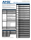
NXC-VAI4 Pinouts, Signals, and Functions
Pin Function Pin Function Pin Function
1 Output #1 (GND) 9 Input #1 (GND) 17 +5 V Reference output (GND)
2 Output #1 10 Input #1 18 +5 V Reference output
3 Output #2 (GND) 11 Input #2 (GND) 19 External Reference input (GND)
4 Output #2 12 Input #2 20 External Reference input
5 Output #3 (GND) 13 Input #3 (GND)
6 Output #3 14 Input #3
7 Output #4 (GND) 15 Input #4 (GND)
8 Output #4 16 Input #4
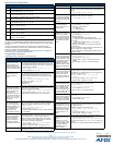
NXC-VAI4 Channel Assignments
Channel State Function
Channel 1 ON While channel 1 is ON, the voltage on Output 1 will ramp up at the
"CURRENT OUTPUT 1 RAMP UP TIME" rate. The voltage ramp
stops if the maximum is reached.
OFF Stops voltage ramping on Output 1 at current value.
Channel 2 ON While channel 2 is ON the voltage on Output 2 will ramp up at the
"CURRENT OUTPUT 2 RAMP UP TIME" rate. The voltage ramp
stops if the maximum is reached.
OFF Stops voltage ramping on Output 2 at current value.
Channel 3 ON While channel 3 is ON the voltage on Output 3 will ramp up at the
"CURRENT OUTPUT 3 RAMP UP TIME" rate. The voltage ramp
stops if the maximum is reached.
OFF Stops voltage ramping on Output 3 at current value.
Channel 4 ON While channel 4 is ON the voltage on Output 4 will ramp up at the
"CURRENT OUTPUT 4 RAMP UP TIME" rate. The voltage ramp
stops if the maximum is reached.
OFF Stops voltage ramping on Output 4 at current value.
Channel 5 ON While channel 5 is ON the voltage on Output 1 will ramp down at the
"CURRENT OUTPUT 1 RAMP DOWN TIME" rate. The voltage
ramp stops if the minimum is reached.
OFF Stops voltage ramping on Output 1 at current value.
Channel 6 ON While channel 6 is ON the voltage on Output 2 will ramp down at the
"CURRENT OUTPUT 2 RAMP DOWN TIME" rate. The voltage
ramp stops if the minimum is reached.
OFF Stops voltage ramping on Output 2 at current value.
Channel 7 ON While channel 7 is ON the voltage on Output 3 will ramp down at the
"CURRENT OUTPUT 3 RAMP DOWN TIME" rate. The voltage
ramp stops if the minimum is reached.
OFF Stops voltage ramping on Output 3 at current value.
Channel 8 ON While channel 8 is ON the voltage on Output 4 will ramp down at the
"CURRENT OUTPUT 4 RAMP DOWN TIME" rate. The voltage
ramp stops if the minimum is reached.
OFF Stops voltage ramping on Output 4 at current value.
Channel 9 ON Reserved [do not use].
OFF Reserved [do not use].
Channel 10 ON While channel 10 is ON the voltage on Output 1 is set to 100%.
OFF Sets Output 1 voltage to 50%.
Channel 11 ON While channel 11 is ON, the voltage on Output 2 is set to 100%.
OFF Sets Output 2 voltage to 50%.
Channel 12 ON While channel 12 is ON, the voltage on Output 3 is set to 100%.
OFF Sets Output 3 voltage to 50%.
Channel 13 ON While channel 13 is ON, the voltage on Output 4 is set to 100%.
OFF Sets Output 4 voltage to 50%.
Channel 14 ON While channel 14 is ON, the voltage on Output 1 is set to 0%.
OFF Sets Output 1 voltage to 50%.
Channel 15 ON While channel 15 is ON, the voltage on Output 2 is set to 0%.
OFF Sets Output 2 voltage to 50%.
Channel 16 ON While channel 16 is ON, the voltage on Output 3 is set to 0%.
OFF Sets Output 3 voltage to 50%.
Channel 17 ON While channel 17 is ON, the voltage on Output 4 is set to 0%.
OFF Sets Output 4 voltage to 50%.
Channel 18 ON While channel 18 is ON, the voltage on Output 1 is set to 75%.
OFF Sets Output 1 voltage to 50%.
Channel 19 ON While channel 19 is ON, the voltage on Output 2 is set to 75%.
OFF Sets Output 2 voltage to 50%.
Channel 20 ON While channel 20 is ON, the voltage on Output 3 is set to 75%.
OFF Sets Output 3 voltage to 50%.
Channel 21 ON While channel 21 is ON, the voltage on Output 4 is set to 75%.
OFF Sets Output 4 voltage to 50%.
Channel 22 ON While channel 22 is ON, the voltage on Output 1 is set to 25%.
OFF Sets Output 1 voltage to 50%.
Channel 23 ON While channel 23 is ON, the voltage on Output 2 is set to 25%
OFF Sets Output 2 voltage to 50%.
Channel 24 ON While channel 24 is ON, the voltage on Output 3 is set to 25%
OFF Sets Output 3 voltage to 50%.
Channel 25 ON While channel 25 is ON, the voltage on Output 4 is set to 25%
OFF Sets Output 4 voltage to 50%.