


Installation Sheet
RDM-2FDB Dual Channel Lutron FDB Ballast Dimmer
1920 W
The RDM-2FDB Dual Channel Ballast Dimmer is a 1920 W positive air gap
relay and dimmer, built for strength and for reliable switching/dimming of
Lutron FDB ballasts. It is designed for use with the RDA series of enclo-
sures, in a AMX Lighting™ modular digital dimming system. The RDM-
2FDB module's 120, 240, and 277 VAC ratings are CE, UL, and C-UL
approved.
RDM-2FDB UL and C-UL Ratings
• 120 VAC, 1920 W
• 240/277 VAC, 1920 W
Suggested Dimmed Loads
• Most 3-wire dimmable fluorescent ballasts
• Lutron
©
Hi-Lume
®
FDB Ballasts
• Lutron Eco-10
®
Ballasts
Specifications:
• Dimensions (HW): 10.0" x 2.75" (25.4 cm x 6.99 cm)
• Dimmed output protected by a 250 mA GMA 5 x 20 mm fuse
• Phase dependant
• Use wires rated at 75°C (167°F)
• Torque terminals to 20 in-lbs. (2.3 N/M)
• Max. wire size: 10 AWG (4 mm²)
• Wire stripping length: 0.28" (7 mm)
• Weight: 1.5 lbs. (0.68 kg)
•BTU/hr: 5
• Control current: 85 mA @ 12 VDC
• For use with FDB ballasts
Caution: Pre-Installation Notes
• All Class 1 wiring must be connected to proper terminals.
• All control wiring must be connected to proper terminals.
• Disconnect power while installing or connecting the unit.
• Keep top and bottom air vents clear at all times.
• Use field installed copper conductors.
• All electrical ratings are for continuous duty.
• For indoor use only.
• This module may require extra power from the AXlink connection or an
external power supply connected to the control card.
Connecting the RDM-2FDB to the AMX Lighting Master
Lighting Application Drawing
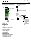
FIG. 1 RDM-2FDB
Relay
Line in (hot)
Switched out
Dimmed out
Fuse
Positive air
gap relay
Relay
Line in (hot)
Switched out
Dimmed out
Low-voltage control wiring:
4-pin connector to AMX
Lighting master controller
Mounting
points
Ballast A
Ballast B
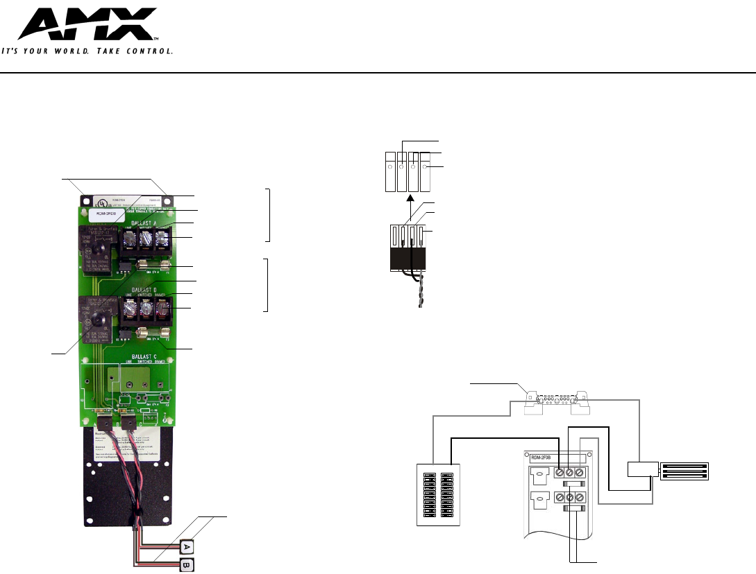
FIG. 2 RDM-2FDB connections
FIG. 3 RDM-2FDB wiring configuration
Pin 3 (RLY)
Pin 2 (DIM)
Pin 1 (+12 V)
RDM-2FDB 4-pin module connector
3 (-)
2 (AC)
1 (+)
4-pin plug from RDM series module
Note: The 4-pin plugs from the module connector
to the 4-pin connector on the master (black plug cover facing up).
BALLAST
Ballast
Circuit breaker
panel
The fuse protects the dimming
circuit from a low impedance
load.
• The fuse would blow if it
were incorrectly wired
• Catastrophic ballast failure
• Reversing switched and
dimmed circuits
• Reversing dimmed and
line circuits.
The dimmed output must be
connected to a high impedance
load.
All neutrals are
common to the
Neutral block in the
enclosure. Provide
a separate neutral
for each load.
Neutral
Line in (HOT)
Switched
Dimmed
Florescent
Ballast
Neutral