


Installation Sheet
RDM-HFDB Heavy Duty FDB Module
2400 W
The RDM-HFDB Heavy Duty FDB Module is a heavy-duty, 2400 W positive
air gap relay and dimmer, built for strength and for reliable switching/dim-
ming of Lutron FDB ballasts. It is designed for use with the RDA series of
enclosures, in a AMX Lighting™ modular digital dimming system. The
RDM-HFDB module's 120, 240, and 277 VAC ratings are CE, UL, and C-UL
approved.
RDM-HFDB UL and C-UL Ratings
• 120 VAC, 2400 W
• 240/277 VAC, 2400 W
Suggested Dimmed Loads
• Lutron
©
FDB Ballasts
• Lutron ECO-10
®
Ballasts (refer to the AMX Lighting instruction manual
for more information)
Specifications:
• Dimensions (HW): 10.0" x 2.75" (25.4 cm x 6.99 cm)
• Phase dependant
• Use wires rated at 75°C (167°F)
• Torque terminals to 20 in-lbs. (2.3 N/M)
• Max. wire size: 10 AWG (4 mm²)
• Wire stripping length: 0.28" (7 mm)
• Weight: 1.50 lbs. (0.680 kg)
• BTU/hr: 150
• Control current: 135 mA @ 12 VDC
• Use Dimming Curve 6 (refer to the Programming AMX Lighting
instruction manual for more information).
• For use with FDB ballasts.
Caution: Pre-Installation Notes
• All Class 1 wiring must be connected to proper terminals.
• All control wiring must be connected to proper terminals.
• Disconnect power while installing or connecting the unit.
• Keep top and bottom air vents clear at all times.
• Test loads for shorts before connecting. Use low-voltage wires with a
300 volt rating or greater.
• Use field installed copper conductors.
• All electrical ratings are for continuous duty.
• For indoor use only.
• This module may require extra power from the AXlink connection or an
external power supply connected to the control card.
Connecting the RDM-HFDB to the AMX Lighting Master
Lighting Application Drawings
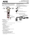
FIG. 1 RDM-HFDB
Low-voltage control
wiring: 4-pin connector
to AMX Lighting master
controller
Solid state relay
Positive air
gap relay
Switched out
Dimmed out
Neutral
Line in (hot)
High
voltage
connections
Mounting points
High
voltage
connections
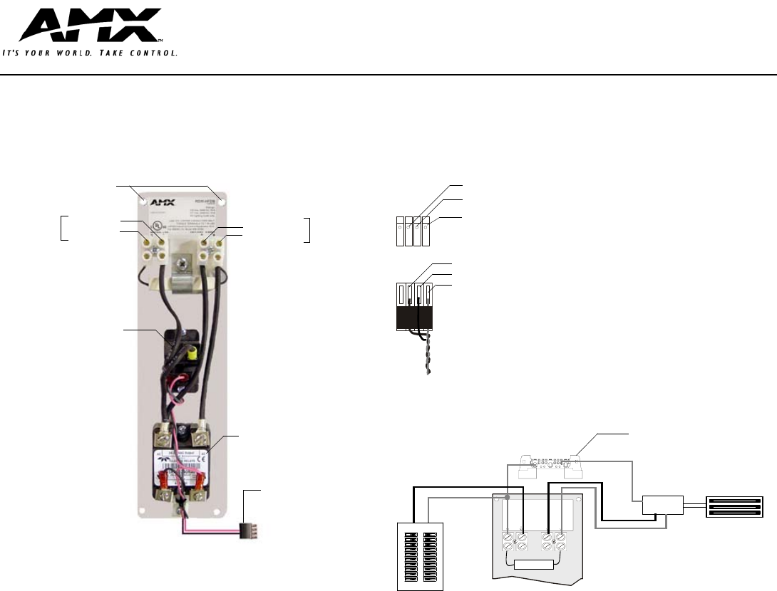
FIG. 2 Connecting the RDM-HFDB and AMX Lighting Master
FIG. 3 RDM-HDC application wiring
Pin 3 (RLY)
Pin 2 (DIM)
Pin 1 (+12 V)
RDM-HFDB 4-pin module connector
1 (+)
2 (AC)
3 (-)
4-pin plug from RDM series module
Note: The 4-pin plugs from the module connector to the 4-pin
connector on the master (black plug cover facing up).
Ballast
Florescent Ballast
Circuit breaker
panel
RDM-HFDB
NEUTRAL LINE SWITCHED DIMMED
Switched
Dimmed
Neutral
Line in (HOT)
All neutrals are common
to the Neutral block in
the enclosure. Provide
a separate neutral for each
Neutral
load.