


Installation Guide
RE-DM4 Radia Eclipse 4-Channel Dimmer Module (120 or 240 volts)
Overview
The RE-DM4 RADIA Eclipse 4-Channel Integrated Dimmer Module (120 VAC:
FG706-01; 240 VAC: FG706-02) controls up to six circuits with four 1200-watt onboard
dimmers and two satellite connectors for RDM series dimmer or switch modules
(FIG. 1). The RE-DM4 is designed for use with the RDA series of enclosures in an
AMX Lighting™ modular digital dimming system. The RE-DM4 is controlled by AXLink
or by dry (contact) closures.
Specifications
Suggested Loads
Caution: Pre-Installation Notes
WARNING: This unit should be installed only by qualified electrical personnel, and in
compliance with all national electrical codes, local codes and ordinances.To prevent
possible personal injury or death, disconnect power to the enclosure at the breaker
box before attempting to work with any AMX Lighting modules.
• All Class 1 and 2 wiring must be connected to their dedicated terminals.
• Class 1 wiring should be connected through the top of the enclosure, and Class
2 wiring through the bottom.
• Load conductors must be same size as line conductors, regardless of
connected load.
• Disconnect power while installing or connecting the unit.
• Keep top and bottom air vents clear at all times, and maintain 12” (30.48 cm)
clearance around the top and bottom.
• Test loads for shorts before connecting.
• Class 2 wiring must be rated 300V or higher.
• For indoor use only.
• AC lighting loads only.
• This module may require extra power from the AXLink connection or an external
power supply connected to the control card.
• For more information, refer to the RE-DM4 instruction manual available at
www.amx.com.
Radia Lighting System Configuration Pages
The AMX Radia Web pages provide a simple interface for users of the Radia Duet
module. The web pages reside on the AMX master when running the Radia Duet
module and may be accessed through Internet Explorer or Mozilla Firefox. The RE-
DM4 may also be configured using NetLinx code or a terminal. For more information,
refer to the RE-DM4 instruction manual available at www.amx.com.
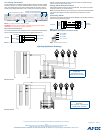
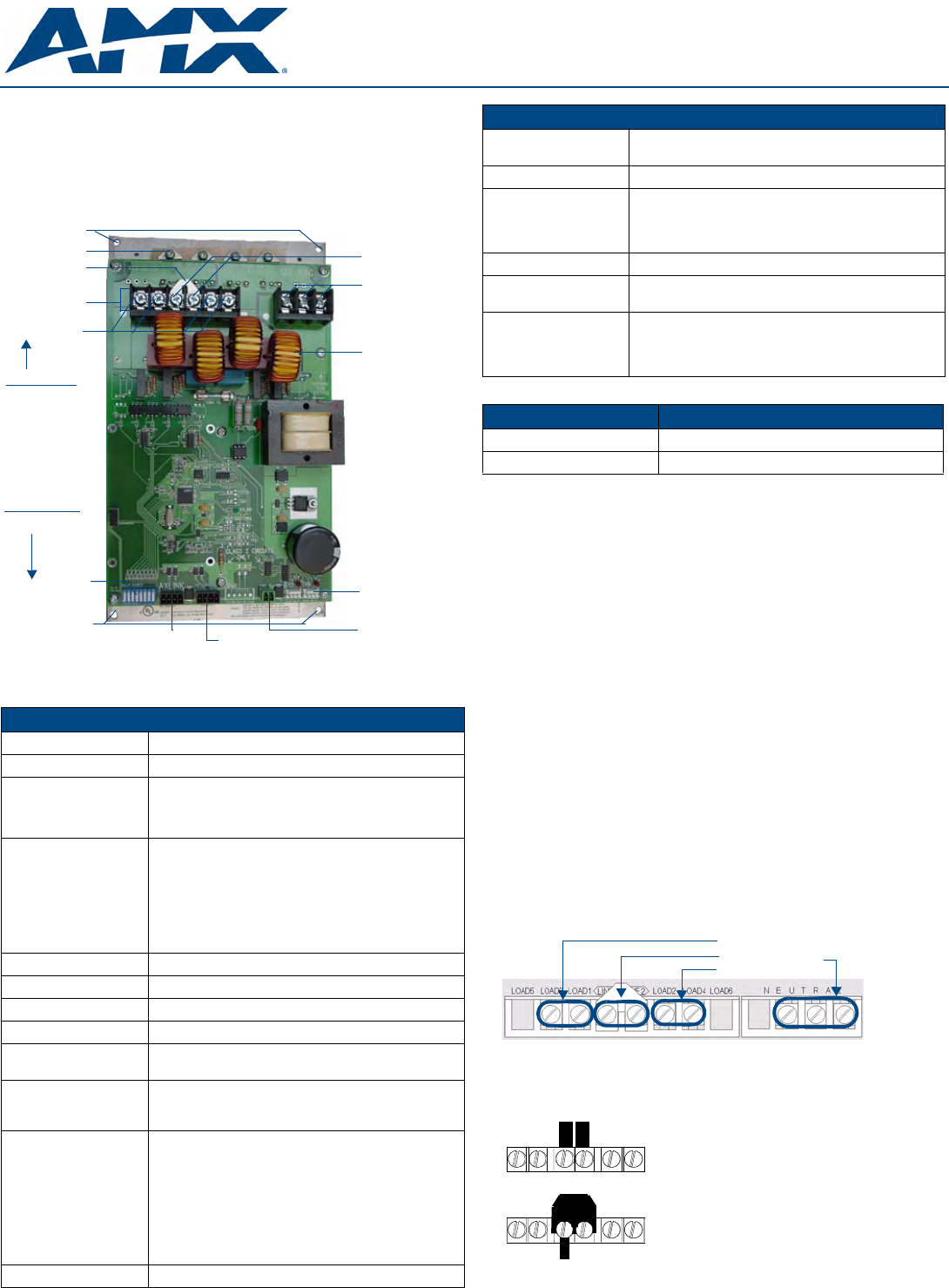
High-Voltage Connections
Each AMX Lighting module has its high-voltage connectors marked on its circuit
board. Line, load, and neutrals are also clearly marked.
Line-in Connections
• Using two feeds for Line 1 and Line 2 provides two 2400 W inputs.
• With a jumper, Line 1 and Line 2 provides a single 2400 W input (FIG. 3).
FIG. 1 RE-DM4 4-Channel Integrated Dimmer Module
RE-DM4 Specifications
Dimensions (HW) 5.75" x 10.0" (146.05 mm x 254.00 mm)
Weight 4.5 lbs (2.04 kg)
Line Input • 120, 240 VAC, single phase, 2W+G, 50/60 Hz, 2400 W,
one feed
• 120, 120/240, 240 VAC, single phase, 3W+G, 50/60
Hz, 4800 W, dual feed
Output • 1200 W max. per channel @120, 240 VAC
• 2400 W max. total, all four channels on with single
2400 W feed
• 4800 W max. total, all four channels on with dual
2400 W feeds
• Line input #1 goes to dimmer 1 and 3; line input #2
goes to dimmer 2 and 4
• All electrical ratings are for continuous duty
Wire rating Use only copper wires rated at 75°C (167°F) min.
Torque terminals To 20 in-lbs (2.3 N/M)
Maximum wire size 10 AWG (4 mm²)
Wire stripping length 0.5" (13 mm)
AXLink Port 4-pin 3.5mm black captive wire connector. AXLink
communication signaling with 12VDC power in.
Aux Power 2-pin 3.5mm green captive wire connector. This is a
12VDC power input that supplies additional power to the
Radia PCB and connected Radia modules.
Dry Contacts • Emergency fire alarm relay connection - Closed relay
activates preset 126. Other control is locked out until
relay opens. Supports daisy chaining of up to 20
dimmers for this connection, with a maximum current
requirement of 200mA when daisy-chained.
• Failsafe connection - Works with a toggle switch -
opening the switch triggers preset 128, closing the
switch triggers preset 127. Supports daisy chaining of
up to 20 dimmers for this connection with a maximum
current requirement of 200mA when daisy-chained.
BTU/hr 300 single feed (2400 W); 600 dual feed (4800 W)
Mounting
Jumper
Load out
Neutral
Chokes
High
Voltage
Mounting
External +12V
Aux Power
AXLink
DIP Switch
Dry Closures
AXlink Connector
Power Devices
points
Connections
Address
points
4-Pin Connectors
to RDM series
Modules
Line In
Class 1 wiring
Class 2 wiring
RE-DM4 Specifications (Cont.)
Idle current draw 75 mA @ 120 VAC, 50 mA @ 240 VAC, 100 mA @ 13.5
VDC
RDM control current 2 at 200 mA @ 12 VDC with no additional power supply
Certifications • FCC
•CE
• UL North America
• IEC-60950 Safety
Operating Temp Range • 0° to 40°C (32° to 104°F)
Included Accessories • 2 4-pin 3.5mm captive wire connector (41-5047)
• 4 #8-32x1/2” F-point mounting screws
Required Enclosures • RDA-ENC2 (FG606-10)
• RDA-ENC4 (FG606-11)
• RDA-ENC6/6B (FG606-12/13/15)
• RDA-ENC12B (FG606-14/16)
Dimmed Switched
Incandescent Motors
Neon, cold-cathode Fans
FIG. 2
High-voltage connections
FIG. 3 Line-in Connections
Neutral
Line in
Load
Load
Dual 2400 W Inputs without jumper
Single 2400 W Input with jumper