APC Back-UPS
®
300, 500, 650 User’s Manual 990-2004E Revision 7 12/99
Inspect
Inspect the UPS and its contents on receipt:
•
User’s Manual
•
UPS
•
Cord straps (2)
•
Telephone cable
•
Warranty card
•
APC Solutions magazine
•
Equipment Protection policy
500 and 650 VA models:
•
PowerChute
®
plus software CD
•
Interface cable
•
Software Install Sheet
The packaging is recyclable, save it for re-use or
dispose of it properly. Please fill out the warranty
registration card to obtain warranty coverage.
Place
Locate the UPS in a protected area that is free of
excessive dust and has adequate air flow. Do not
operate the UPS where the temperature and
humidity is outside specifications.
Connect UPS to power
Connect the battery
Refer to "Battery replacement procedure"- pg. 2
Charge the battery
The UPS battery charges whenever it is connected to
utility power and typically requires less than five hours
to charge fully. UPS capacity is reduced until the
battery is fully charged.
Check site wiring fault
indicator (rear panel-top)
A lit indicator means that a shock hazard exists due to
faulty building wiring , that should be corrected by a
qualified electrician.
If the building wiring fault indicator is lit, one of the
following conditions exist:
•
Open or high resistance ground
•
Hot and neutral polarity reversal
•
Overloaded neutral circuit
Note: Improper building wiring will not prevent the
UPS from operating but will limit it's protection
capability. Faulty building wiring could result in
equipment damage that is not covered by APC. Please
refer to APC's Equipment Protection Policy for details.
Connect phone cables to
surge protection (optional)
Socket Location:
Rear panel of 500 and 650 VA models only.
Surge protection is provided for one phone line when
it is connected as shown below:
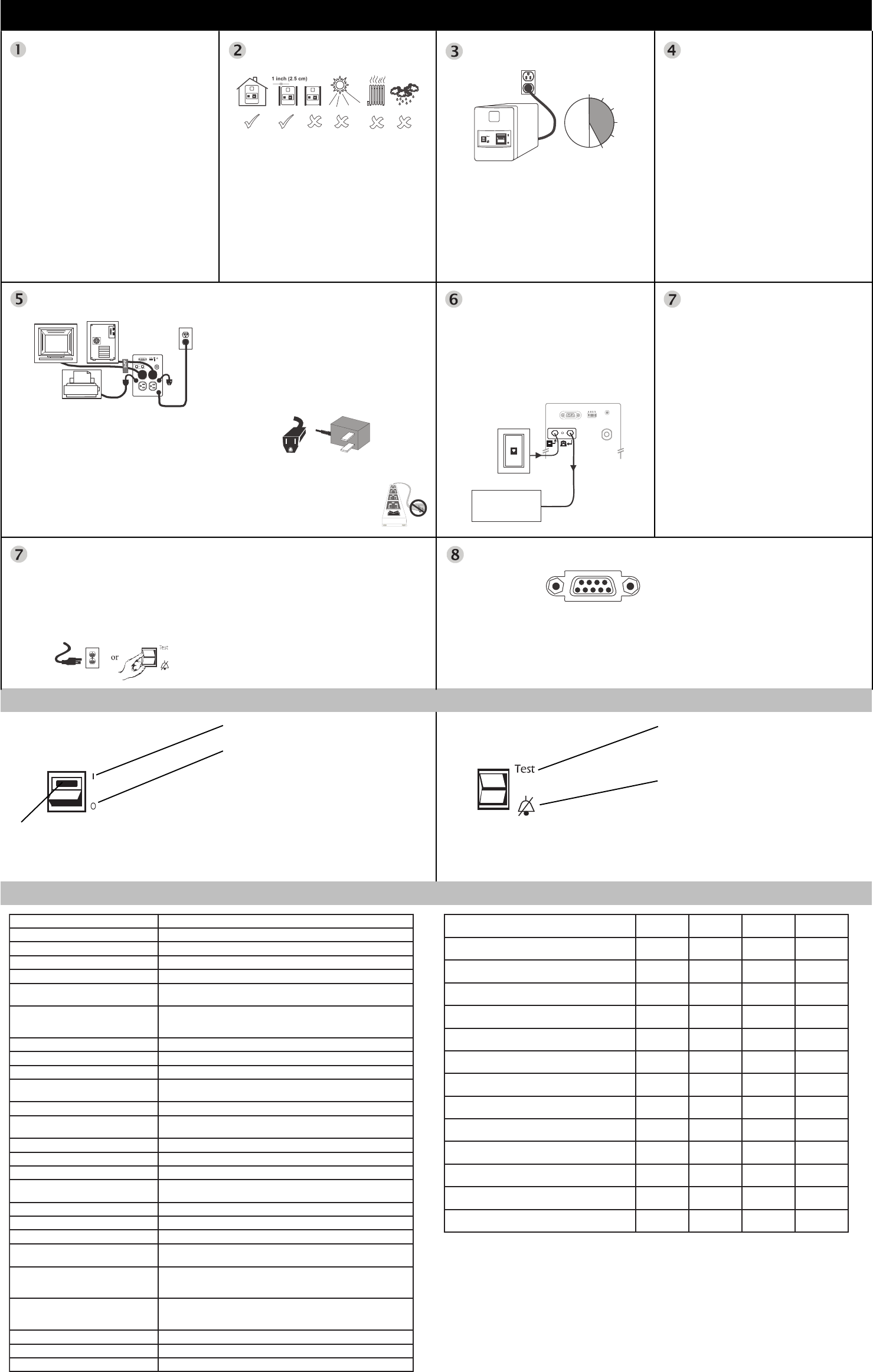
Switch "On" and test the UPS
Press the upper portion of the Power 1/0 switch and
then switch "On" the equipment connected to the UPS.
The Power 1/0 switch should be lit. Utility power is
supplied to the equipment.
Perform a simulated utility blackout test to confirm the
UPS unit can switch from utility power to battery
power and back again, without affecting equipment
powered by the UPS.
Connected equipment must be "On".
Continued
Connect equipment
Cord Straps: Straps are provided to keep cords from
tangling and taking up too much space.
Battery Back-Up Outlets:
•
Surge protection when utility power is used
•
Battery power and surge protection when utility
voltage is outside acceptable limits.
Data-sensitive equipment such as a computer, monitor,
or external drive are connected to these outlets.
Accessory Surge Protection Outlets (500 and 650
VA models only): These outlets are for equipment that
need surge protection but do not need power during a
utility outage (like an inkjet printer or a scanner).
BlockSafe™ Outlets (500 and 650 VA models only):
Corded sockets are provided which accept "block type"
plugs without covering other outlets. Some printers and
external disk drives have block type plugs that look
similar to the one below.
Caution: Do not connect a surge
suppressor or laser printer to the UPS.
These devices may overload the UPS.
Continued
Start the test by either:
•
Unplugging the UPS power cord, or
•
Pressing and holding the "Test" portion of the Test/
Alarm Disable switch (500 and 650 VA models
only).
1. The UPS will then beep once every five seconds (or
continuously) to remind you that your equipment is
powered by a limited capacity power source.
2. Restore power to the UPS by releasing the Test
switch or by reconnecting the UPS power cord.
If the equipment operation was undisturbed throughout
the testing, the system is operating properly.
Connect computer interface cable (optional)
Socket Location:
Rear panel of UPS
Note: 300 VA model users must purchase software and
cable separately. Call APC at the number listed at the
bottom of Page 2, and ask for software kit AP9015.
Connect the interface cable to the computer interface
port on the rear panel of the UPS. Connect the other
cable end to an unused serial port socket on the
computer and install the PowerChute® plus software
(see software documentation for detailed instructions).
Power 1/0 Switch
The Power 1/0 Switch controls
power to the UPS.
Lamp: The lamp in the Power 1/0 Switch is lit
whenever normal utility voltages are present at the
power sockets.
1 The UPS operates and all connected devices are
powered.
0 The UPS is de-energized and all devices connected
to battery backup outlets are unpowered
All devices connected to battery back-up outlets can
be switched "On" or "Off" using this switch, if each
device's power switch is left in the "On" position.
Note: Accessory surge protected outlets are
unaffected by this switch - they remain powered as
long as utility power is available.
Test/Alarm Disable Switch
Switch Location: Front panel of
500 and 650 VA models only.
The battery run time can be checked by pressing and
holding the "Test" switch and waiting to see how long
the UPS provides power to the equipment before the
low battery warning is sounded.
Test
Press the "Test" portion of the Test/Alarm Disable
Switch to simulate a power outage - the UPS battery
supplies power to the equipment
Alarm Disable
The UPS will emit a beep once every five seconds
during a utility power outage, unless the alarm is
disabled by pressing this side of the switch. The UPS
low battery warning (a loud continuous tone) will still
sound in the event of an extended utility outage.
Specifications RunTime (minutes) vs. Power Demand
egatloVtupnIelbatpeccA esahPelgniS,caV051-0
egatloVrefsnarT )rewoltesebyam(caV301
egatloVtuptuO caV121-901
noitcetorPtnerruCrevOtupnI rekaerbtiucricelbatteseR
)enilno(stimiLycneuqerF )gnisnesotua(zH36-75
emiTrefsnarT
)emitesnopsertuokcalb(
sm8
daoLmumixaM
AV003 W081-
AV005 W033-
AV056 W004-
egatloVtuptuOyrettab-nO caV511
ycneuqerFyrettab-nO tuonworbgnirudytilituotdezinorhcnyssselnuzH26-85
epahsevaWyrettab-nO evaw-enisdeppetS
noitcetorPtnerruCrevOtuptuO
nonwodtuhsgnihctal,detcetorptiucric-trohsdnatnerrucrevO
daolrevo
epyTyrettaB dica-daeldelaes,eerfecnanetniam,foorpllipS
efiLyrettaBlacipyT
dnaselcycegrahcsidforebmunnognidneped,sraey6ot3
erutarepmettneibma
emiTegrahceRlacipyT egrahcsidlatotmorfsruoh01ot5
erutarepmeTgnitarepO )C°04ot0(F°401ot23
erutarepmeTegarotS )C°54ot51-(F°311ot5
evitaleRegarotSdnagnitarepO
ytidimuH
gnisnednoc-non,%59ot0
noitavelEgnitarepO )m000,3+ot0(tf000,01+ot0
noitavelEegarotS )m000,51+ot0(tf000,05+ot0
)m1(tf3taesioNelbiduA ABd04<
)DxWxH(eziS
AV005,AV003 )mc3.33x6.8x1.51("1.31x"4.3x"0.6:
:AV056 )mc1.63x9.11x8.61("2.41x"7.4x"6.6
thgieW
AV003 )gk0.6(bl1.31
AV005 )gk0.7(bl4.51
AV056 )gk5.01(bl0.32
thgieWgnippihS
AV003 )gk1.7(bl7.51
AV005 )gk2.8(bl0.81
AV056 )gk0.21(bl5.62
snoitacifitreCdnagnitsiL 86trapdna51trapCCF,1.701ASC,8771LU
noitacifireVIME deifitrecBssalCCCF
ytinummIcitengamortcelE IIIlevel5-108dna,VIlevel4-108,3-108,2-108CEI
noitpircseDmetsyS
dnameD
)sttaW(
SPU-kcaB
003
SPU-kcaB
005
SPU-kcaB
056
684potkseD
rotinoM"51ro"41/w
501612273
muitnePrewoTiniM/potkseD
rotinoM"51ro41/w
011410243
muitnePrewoTiniM/potkseD
rotinoM"71/w
031017162
orPmuitneP/IImuitnePrewoTiniM/potkseD
rotinoM"51ro41/w
031017162
orPmuitneP/IImuitnePrewoT
rotinoM"51ro"41/w
05184112
muitnePrewoT
rotinoM"71/w
05184112
orPmuitneP/IImuitnePrewoTiniM/potkseD
rotinoM"71/w
05184112
muitnePrewoTiniM/potkseD
rotinoM"12/w
07162171
orPmuitneP/IImuitnePrewoT
rotinoM"71/w
07162171
6KrewotiniM/potkseD
rotinoM"12/w
08160151
muitnePrewoT
rotinoM"12/w
091-941
orPmuitneP/IImuitnePrewoTiniM/potkseD
rotinoM"12/w
091-941
orPmuitneP/IImuitnePrewoT
rotinoM"12/w
012-711
yamerutarepmetgnitarepodetaveledna,esuevissecxe,egayrettaB.etamixorppaeraseulavesehT:etoN
.gnizis/moc.cpa.www//:ptthtadnuofebnacnoitamrofnieroM.emitnurSPUesaercedrehtruf
5 hours
Phone Line
Modem/Fax/Phone
System


