3-16kVA Service Bypass Panels
©2009 APC by Schneider Electric, APC, the APC logo, and Smart-UPS are
owned by Schneider Electric industries S.A.S American Power Conversion
Corporation, or their affiliated companies. All other trademarks are property
of their respective owners.
990-1530B
Note: Read the safety information sheet before installation.
Illustrations in this document may differ slightly from the actual hardware.
Attention: This product is for use in a controlled environment. Refer to product
specifications for environmental limits.
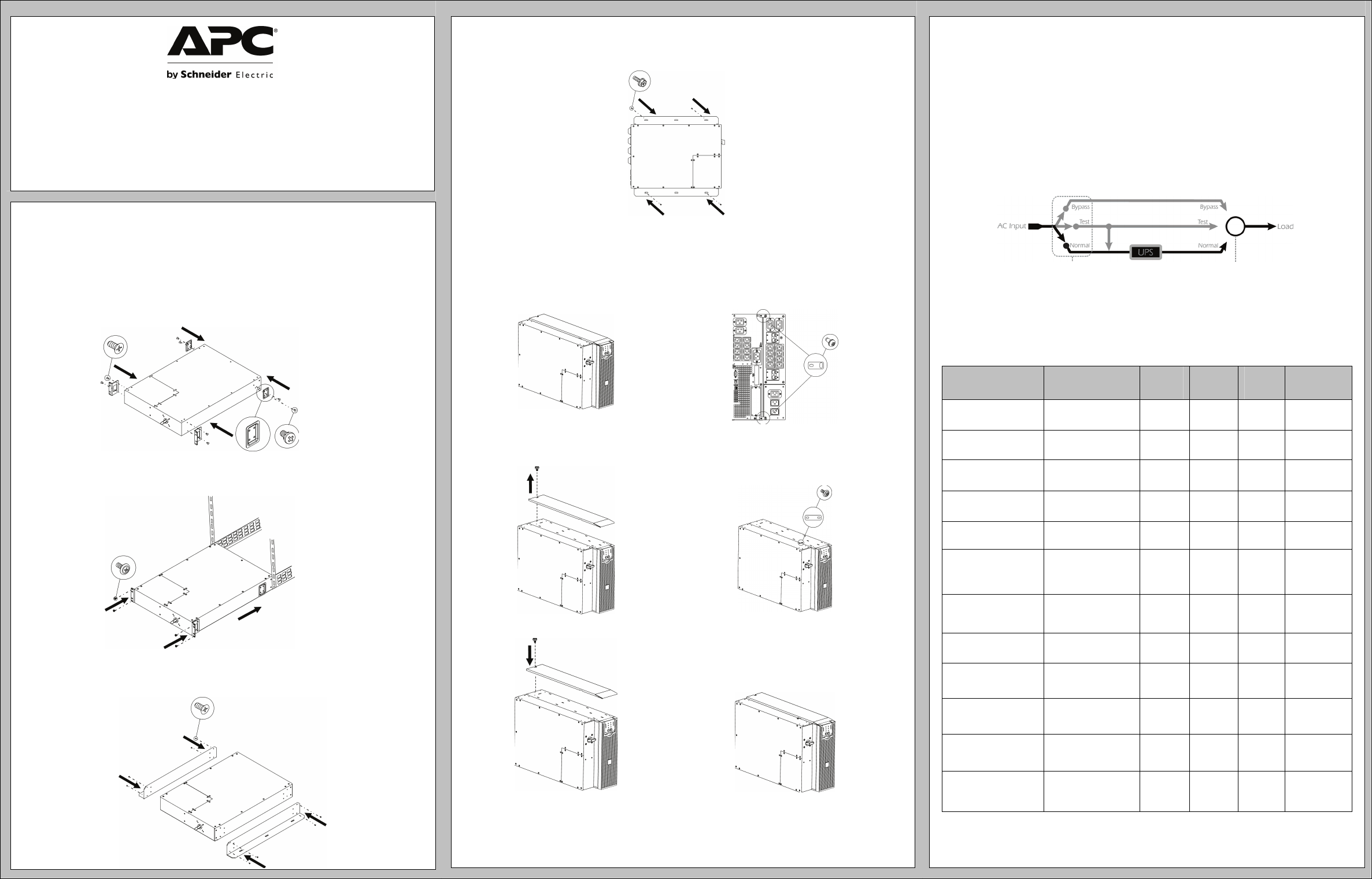
RACK MOUNTING
n
o Set SBP in the rack. If hardwiring is required, see Connecting Power
section before screwing into the rack.
WALL MOUNTING
n
o Whenever possible, attach one top screw and one bottom screw into a wall stud. If stud
mounting is not possible, use an expandable wall anchor. Screws are not included; .25” x
2” lag bolts are recommended.
TOWER OPTION (FOR SMART-UPS RT SETUPS ONLY)
n Remove screw from the top and bottom rear of both the UPS and SBP. Install tie
brackets and reattach screws.
o Unscrew and remove top cover of the
UPS.
p Attach bracket to top of UPS and SBP.
q Reattach top cover of the UPS.
Note: The SBP5000RMI2U, when used in conjunction with an SURT3000XLI or SURT5000XLI UPS in a
tower configuration without an external battery pack (SURT192XLBP), is suitable for mounting on
concrete or other non-combustible smooth surfaces only.
USER CONFIGURABLE
Attention: When using an online UPS, put the UPS in automatic bypass mode before
rotating the SBP switch.
1. Normal: Power is directed from the utility outlet, through the Bypass Panel and UPS,
and to connected equipment. For use during normal UPS operation.
2. Test: Power supplied to the UPS is not output. Use when tests are being conducted on
the UPS, and connected equipment is not yet desired.
3. Bypass: Power from the utility outlet is filtered through the Bypass Panel, and to the
connected equipment. Use to bypass the UPS, when functioning improperly.
Note: While operating in ‘Test’ or ‘Bypass’ mode, power to the connected equipment is
not conditioned by the UPS. At this time, the “Equipment Protection Policy” is not valid.
IDENTIFYING THE PANEL
Service Bypass Panels will differ. Refer to chart for unit specifications.
Note: HW= Hardwire
Service Bypass
Panel
Corresponding
UPS Systems
Bypass
Input
UPS
Input
UPS
Output
PDU
Panel
SBP3000RM2U
100-120V Smart-UPS
3kVA
L5-30P L5-30R L5-30P (2) 5-20R,
(6) 5-15R
SBP5000RMT2U
200/208/240V
Smart-UPS 3-4.5kVA
L6-30P L6-30R L6-30P (2) L6-20R,
(2) L6-30R
SBP5000RMI2U*
230V Smart-UPS
3-5kVA
C20/HW C19/HW C20/HW (2) C19,
(8) C13
SBP6KRMT2U**
200/208/240V
Symmetra 2-6kVA
L6-30P/
HW
L6-30R/
HW
L6-30P/
HW
(1) L6-20R,
(2) L6-30R
SBP6KRMI2U
230V Symmetra
2-6kVA
HW HW HW (4) C19
SBP3000
100-240V Smart-UPS
3-5kVA with 30A HW
input/output
available
HW HW HW HW
SBP10KRMT4U
200/208/240V
Smart-UPS RT
7.5-10kVA
HW HW HW (3) L6-20R,
(3) L6-30R
SBP10KRMI4U
230V Smart-UPS RT
7.5-10kVA
HW (3Ph
or 1Ph)
HW (3Ph
or 1Ph)
HW (8) C13,
(2) C19
SBP16KP
200-240V
Symmetra LX
4-16kVA
HW (3Ph
or 1Ph)
HW (3Ph
or 1Ph)
HW HW
SBP16KRMI4U
220-240V
Symmetra LX
4-16kVA
HW (3Ph
or 1Ph)
HW (3Ph
or 1Ph)
HW (3) 30A HW
SBP16KRMP4U
200/208/240
Symmetra LX
4-16kVA
HW HW HW (6) L14-30R
SBP16KRMP4U-HW
200/208/240
Symmetra LX
4-16kVA
HW HW HW (1) L14-30R,
(3) L5-20R,
(1) 100A HW
*For loads exceeding 3kVA, hardwiring is necessary.
**For loads exceeding 5kVA, hardwiring is necessary.
x4
x4
x4
x8
Rea
Front
x1
x4
x8
x2
x2
x2


