CHAPTER 2
Hardware Modifications
10
200 MB Hard Disk Drive
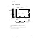
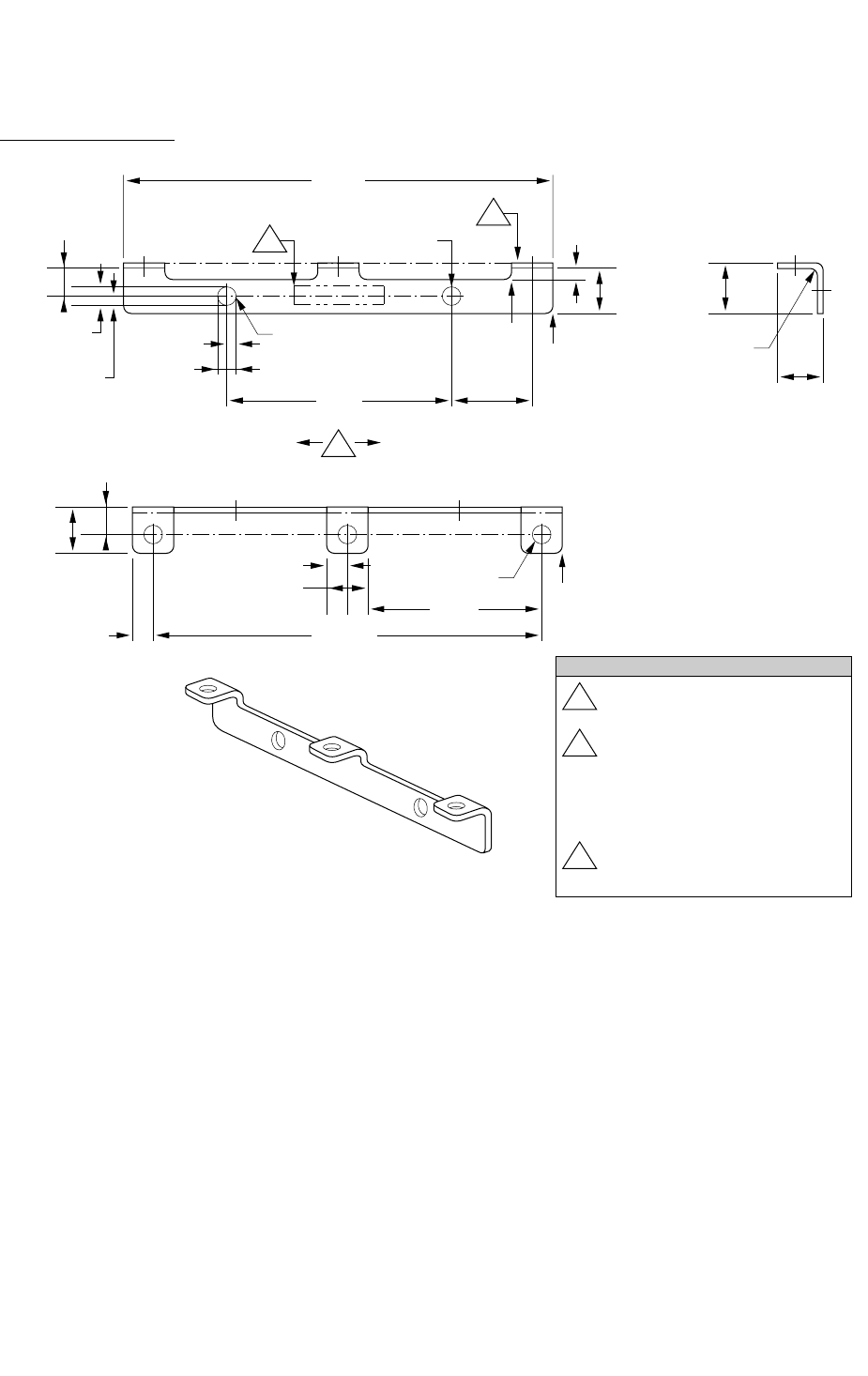
Figure 2-2
Bracket for the hard disk drive
2.874"
(73.00mm)
0.299"
(7.60mm)
2x 0.079"
(2.00mm)
0.125"
(3.20mm)
(1.60mm)
0.188"
(4.795±0.125mm)
0.549"
(13.95mm)
1.5"
(38.10mm)
0.082"
(2.10mm)
0.165"
(4.20mm)
2x R full
4x R
0.039"
(1.00mm)
2x R 0.059"
(1.50mm)
C
L
1
3
0 0.125"
(3.200mm)
2
(8.60)
(7.80)
3x R 1.00
2.598"
(66.00mm)
1.299"
(33.00mm)
3x 0.137"
(3.50mm)
3x 0.275"
(7.00mm)
0.137"
(3.50mm)
3x 0.307"
(7.80mm)
0.192"
(4.900±0.125mm)
3x 0 0.118"
(3.00mm)
6x R 0.059"
(1.50mm)
3 Arrow indicates direction of
material grain.
This surface to be free of burrs
and sharp edges.
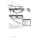
1.
Interpret dimensions and tolerances per
ANSI Y14.5M-1982
2.
Material: CRS 1010-1020, 1.00 ± 0.05 (.0394 ± .0020) thick.
3.
Finish: Zinc pre-plate per Mil.Spec. QQ-Z-325a Class 3 (0.00020) type II.
1
Mark part number, rev level,
vendor I.D., and date code
with 0.19±0.06 high
permanent contrasting
characters.
Locate where shown.
4.
Maximum burr allowance is 15% of material thickness.
5.
Tooling required to make this part to be property of Apple Computer, Inc. and
shall be permanently marked with Apple’s name and appropriate part number.
6.
All dimensions apply after finish.
Notes:
Key
2


