


D-13550-A2-GB20-10 February 1995
Pin Assignments
Overview D-1. . . . . . . . . . . . . . . . . . . . . . . . . . . . . . . . . . . . . . . . . . . . . . . . . . . . . . . . . . . . . . . . . . . . . . . . . .
Overview
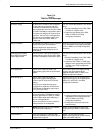
Pin assignments for the 3550 Series DSU connectors
and interfaces are included here. Refer to them as needed.
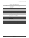
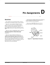
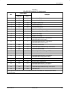
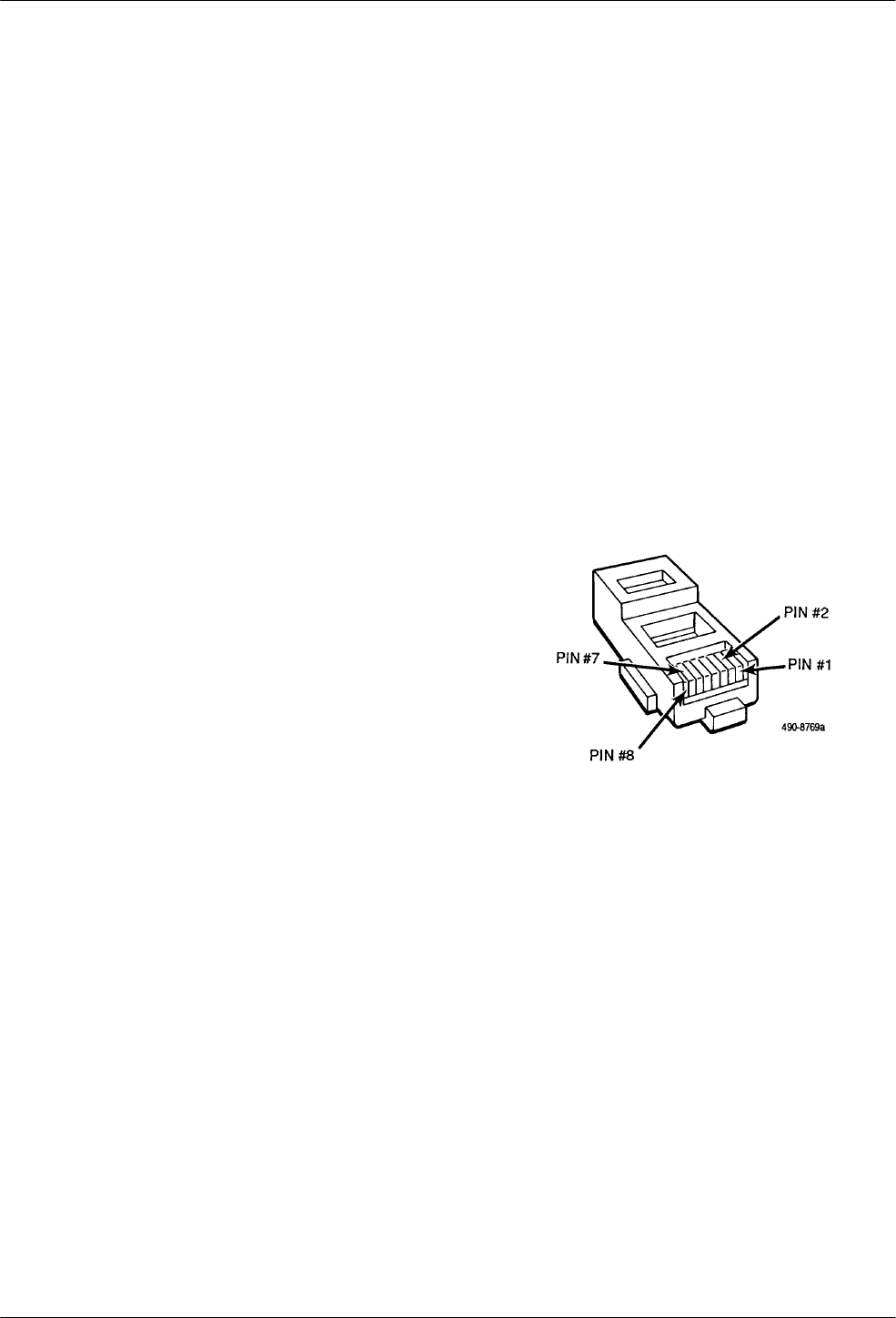
Figure D-1 shows the Model 3550 DSU’s digital
network connector, which is used for DDS connection;
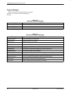
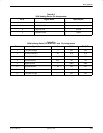
Table D-1 provides its pin assignments. Table D-2
provides the network connector pin assignments used for
the V.32 DBM, which uses a 6-pin jack (not shown in any
figure).
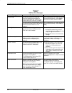
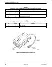
Figure D-2 shows the 3600 Hubbing Device; Table D-3
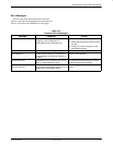
shows its pin assignments. Table D-4 provides the
3600 Hubbing Device’s CC IN/DC OUT jack pin
assignments.
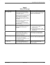
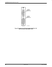
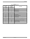
Figure D-3 shows the Model 3551 DSUs rear
connector plate; Table D-5 provides the EIA-232/V.24
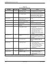
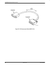
connector’s pin assignments. Figure D-4 shows the V.35
Interconnect Cable that is shipped with the rear connector
plate; it provides the interface between the port’s D-type
connector and the DTE cable’s V.35 connector; Table D-6
provides the 25-pin V.35 connector and the V.35
Interconnect Cable’s pin assignments.
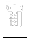
Figure D-5 shows the EIA-232-D crossover cable and
its pin assignments, and Figure D-6 shows the V.35
crossover cable and its pin assignments.
Refer to the COMSPHERE 3000 Series Carrier,
Installation Manual for additional pin assignments.
Figure D-1. Digital Network Connector
D