


COMSPHERE 3550 Series Data Service Units
2-2 February 1995 3550-A2-GB20-10
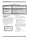
circuit must be capable of supplying a minimum of
2 amperes at 115 Vac. Refer to the Technical
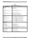
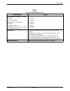
Specifications section in Chapter 1 for additional power
requirements.
CAUTION
The ac transformer contains a
3-wire grounding-type plug which
has a grounding pin. This is a
safety feature. Do not defeat the
purpose of the grounding plug by
modifying it or by using an
adapter.
Prior to installation, use an outlet
tester to check the ac receptacle
for earth ground. If the power
source does not provide a ground
connection, consult an electrician
to determine another method of
grounding the DSU before
proceeding with the installation.
Before connecting the DSU, you need to contact the
telephone company to coordinate your installation before
connecting the DSU to their network. The DSU can only
be operated at the data rate for which access to the DDS
network is provided. If a DBM is installed, the DSU must
also be connected to the dial network. You must notify the
telephone company before you connect to the dial
network. Refer to the notice at the front of this guide to
ensure compliance with FCC, Bell Canada, and Canadian
DOC rules.
No on-site assembly of the DSU is required. However,
installation should not proceed if any of the following is
missing:
• A power cord with table-top ac transformer
• A 14-ft cable for connection to the DDS network,
with 8-pin RJ48S modular plug on each end
For Canadian purchasers, an 8-pin RJ48S connector is
on one end while a 6-pin connector is on the other is
required (order feature number 3000-F1-006).
If the DSU is equipped with a DBM, a dial interface
cable should have been ordered.
• Permissive (RJ11C) – a 6-pin modular plug at each
end (feature number 4400-F1-53x or 3600-F3-503).
• Programmable (RJ45S) – an 8-pin modular plug at
each end (feature number 4400-F1-54x).
Contact your AT&T Paradyne representative if any of
these items is missing from the shipping container, or to
order the appropriate dial interface cable.
If your DSU is equipped with a DBM, you may need to
change the DSU’s hardware straps before installing the
DSU.
How to Change
Hardware Straps
HANDLING PRECAUTIONS
FOR
STATIC SENSITIVE DEVICES
AT&T Paradyne products are
designed to protect sensitive
components from damage due to
electrostatic discharge (ESD) during
normal operation. When
performing installation procedures,
however, take proper static control
precautions to prevent damage to
equipment. If you are not sure of the
proper static control precautions,
contact the nearest AT&T Paradyne
Customer Support office.
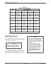
The Model 3550 DSU has a switch located behind its
diagnostic control panel (DCP). This switch contains two
straps, one that controls the permissive or programmable
connection when a DBM is installed, and one that controls
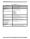
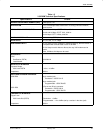
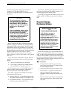
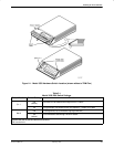
the frame-to-signal grounds. Table 2-1 shows the DSU’s
settings. Refer to Figure 2-1 and the following steps if you
need to change one of these straps.
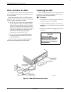
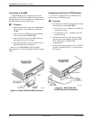
Procedure
1. With your thumbs under the edge of the front
bezel, firmly press upward to lift the bezel from
the tabs securing it in place.
2. Swing the front bezel up and set the bezel aside.
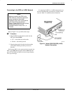
3. Refer to Table 2-1 to determine which switch
needs to be changed. Then, using a small
instrument, carefully change the position of the
switch.
4. Reinsert the front bezel’s hinge tabs into position
and swing the bezel down. Snap the bezel back
into place.