


COMSPHERE 3550 Series Data Service Units
2-6 February 1995 3550-A2-GB20-10
Connecting to the NMS
A 3600 Hubbing Device is required to connect the
control DSU to the 6700 Series NMS. When connected to
the NMS, the DSU can be controlled and configured from
the NMS rather than from the DCP alone.
Procedure
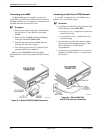
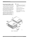
1. Plug the 4-pin modular plug of the 3600 Hubbing
Device (Figure 2-3) into the DSU jack labeled
CC/DC.
2. Plug one end of an M6BJ cable into the hubbing
device jack labeled CC IN/DC OUT.
3. Plug the other end of the 8-pin M6BJ cable into
the 8-pin end of the 873A adapter.
4. Plug the D-type end of the 873A adapter into the
appropriate 6700 Series NMS jack.
Refer to your COMSPHERE 6700 Series NMS
documentation to control and configure the DSU from the
NMS.
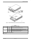
Figure 2-3. Model 3550 DSU NMS Connection
Connecting to the Dial (or PSTN) Network
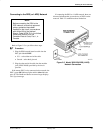
If your DSU is equipped with a V.32 DBM, refer to
Figure 2-4 as you follow these steps.
Procedure
1. Plug either end of the dial (analog) interface cable
into the DSU jack labeled BACKUP.
• Permissive service – telephone cord with 6-pin
modular RJ11C plug
• Programmable service – telephone cord with
8-pin RJ45S plug
2. Plug the other end of the cable into the modular
jack provided by the telephone company, USOC
RJ11C (permissive) or USOC RJ45S
(programmable).
3. If your site has programmable service, verify that
the DSU’s hardware strap S1-1 is switched to the
OFF position.
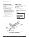
Figure 2-4. Model 3550 DSU
Dial (PSTN) Network Connection