


Installing the Model 3550 DSU
2-73550-A2-GB20-10 February 1995
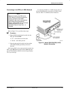
Connecting to the DDS (or LADS) Network
NOTE
Before connecting the DSU to the
DDS network, ensure that approved
primary protectors have been
installed on the circuit in accordance
with Article 800 of the National
Electric Code, NFPA 70, in the United
States and Section 60 of the
Canadian Electric Code, Part 1, in
Canada.
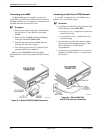
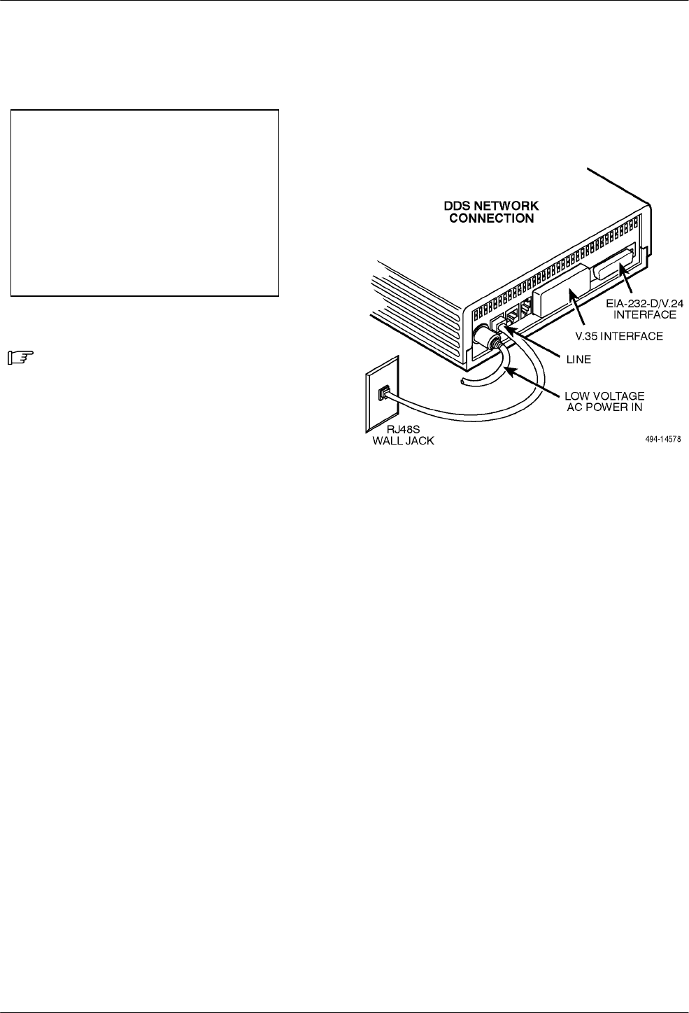
Refer to Figure 2-5 as you follow these steps.
Procedure
1. Plug the DDS network interface cable into the
DSU jack labeled LINE.
• U.S. – select either end of the cable
• Canada – select the 8-pin end
2. Plug the other end of the cable into the modular
jack (USOC RJ48S) provided by the circuit
provider.
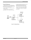
If the remote DSU is also connected to the network, the
DSU’s green OK indicator lights and the Alrm indicator
goes off. The Health and Status screen no longer displays
a No Signal message.
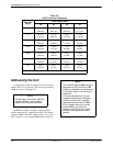
If connecting the DSU to a LADS network, there are
distance limitations that govern the use of DSUs on the
network. Table 2-2 summarizes these limitations.
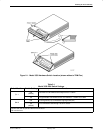
Figure 2-5. Model 3550 DSU DDS (LADS)
Network Connection