


3-13550-A2-GB20-10 February 1995
Installing the Model 3551 DSU
Overview 3-1. . . . . . . . . . . . . . . . . . . . . . . . . . . . . . . . . . . . . . . . . . . . . . . . . . . . . . . . . . . . . . . . . . . . . . . . . .
Before You Begin 3-2. . . . . . . . . . . . . . . . . . . . . . . . . . . . . . . . . . . . . . . . . . . . . . . . . . . . . . . . . . . . . . . . . . .
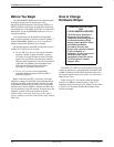
How to Change Hardware Straps 3-2. . . . . . . . . . . . . . . . . . . . . . . . . . . . . . . . . . . . . . . . . . . . . . . . . . . . . . .
Installing the DSU 3-5. . . . . . . . . . . . . . . . . . . . . . . . . . . . . . . . . . . . . . . . . . . . . . . . . . . . . . . . . . . . . . . . . . .
Power-Up Routine 3-8. . . . . . . . . . . . . . . . . . . . . . . . . . . . . . . . . . . . . . . . . . . . . . . . . . . . . . . . . . . . . . . .
Connecting to the Network 3-8. . . . . . . . . . . . . . . . . . . . . . . . . . . . . . . . . . . . . . . . . . . . . . . . . . . . . . . . . . . .
Connecting to the NMS 3-8. . . . . . . . . . . . . . . . . . . . . . . . . . . . . . . . . . . . . . . . . . . . . . . . . . . . . . . . . . . .
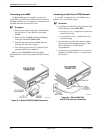
Connecting to the Dial (or PSTN) Network 3-8. . . . . . . . . . . . . . . . . . . . . . . . . . . . . . . . . . . . . . . . . . . .
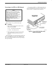
Connecting to the DDS (or LADS) Network 3-9. . . . . . . . . . . . . . . . . . . . . . . . . . . . . . . . . . . . . . . . . . .
Connecting the DSU to a DTE 3-9. . . . . . . . . . . . . . . . . . . . . . . . . . . . . . . . . . . . . . . . . . . . . . . . . . . . . . . . .
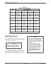
Addressing the Unit 3-9. . . . . . . . . . . . . . . . . . . . . . . . . . . . . . . . . . . . . . . . . . . . . . . . . . . . . . . . . . . . . . . . .
Tributary DSU Addressing 3-10. . . . . . . . . . . . . . . . . . . . . . . . . . . . . . . . . . . . . . . . . . . . . . . . . . . . . . . . .
Verifying Operation and Testing Connections 3-10. . . . . . . . . . . . . . . . . . . . . . . . . . . . . . . . . . . . . . . . . . . . .
To Connect the SDCP to a DSU 3-11. . . . . . . . . . . . . . . . . . . . . . . . . . . . . . . . . . . . . . . . . . . . . . . . . . . . .
Verifying Network Addresses, the Network, and DBM Operation 3-11. . . . . . . . . . . . . . . . . . . . . . . . . . .
Other Tests 3-12. . . . . . . . . . . . . . . . . . . . . . . . . . . . . . . . . . . . . . . . . . . . . . . . . . . . . . . . . . . . . . . . . . . . . .
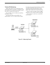
Overview
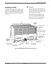
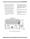
A Model 3551 DSU is designed for installation in a
COMSPHERE 3000 Series Carrier, which supplies power
and provides the interfaces for connecting to the DDS or
dial networks. Up to 16 DSUs can be installed in the
carrier. Refer to the COMSPHERE 3000 Series Carrier,
Installation Manual for additional carrier and installation
information.
The DSU is delivered ready to install in the carrier. It is
configured as a control DSU for operation at 9.6 kbps on a
multipoint circuit.
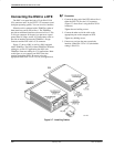
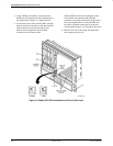
A rear connector plate, which is installed onto the rear
of the carrier, is shipped with the DSU. The rear connector
plate contains two connectors: a 25-pin EIA-232-D/V.24
connector and a 25-pin V.35 connector. Once installed, the
DSU can be removed from the front of the carrier without
disconnecting the DTE cables.
Installation of the DSUs and carrier-related equipment
consists of the following steps, which should be
performed in the order listed.
• Hardware straps
• DSU physical installation
• Network diagnostic connection
• Software configuration
• DDS network (or LADs) connection
• Dial (or PSTN) network connection
(if a DBM is installed)
• DSU DTE connection
• Verification testing
3