


COMSPHERE 3550 Series Data Service Units
3-6 February 1995 3550-A2-GB20-10
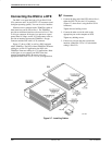
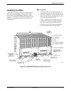
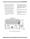
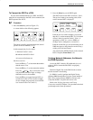
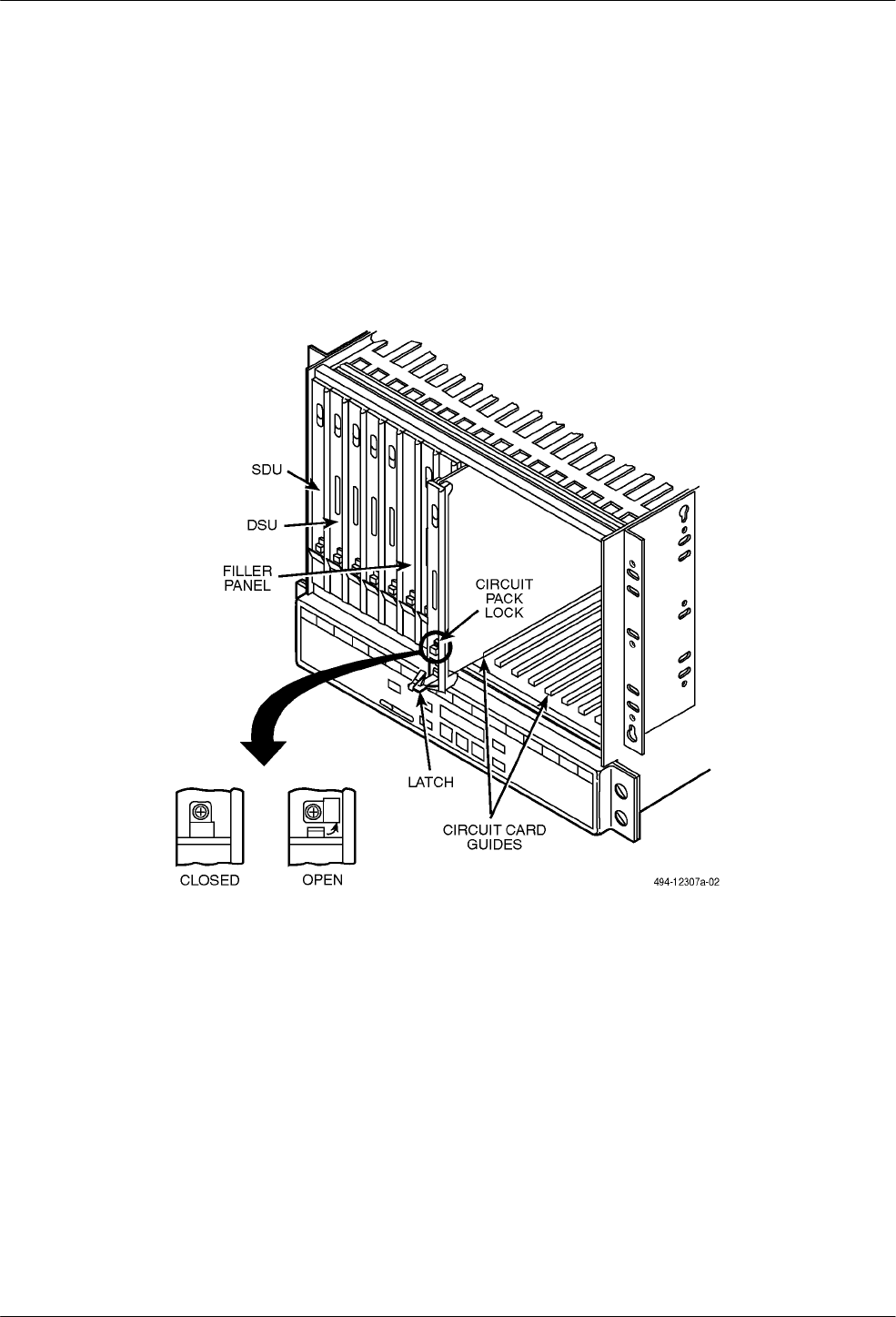
4. Using a Phillips screwdriver, loosen the screw
holding the circuit pack lock and rotate the lock to
the open position (Figure 3-3). Open the latch.
5. At the front of the carrier, hold the DSU vertically
with the latch on its faceplate in the open position.
Then, insert the circuit card into the top and
bottom circuit card guides for the slot that
contains the rear connector plate.
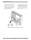
Slide the DSU into the slot, aligning the circuit
card with the rear connector plate until the
connectors seat firmly into the back of the carrier.
Press the faceplate latch to secure the DSU into
the carrier, rotate the circuit pack lock into the
closed position (Figure 3-3), and tighten the screw.
6. Return to the rear of the carrier and tighten the
rear connector plate screw.
Figure 3-3. Model 3551 DSU Installation and Circuit Pack Lock