


COMSPHERE 3550 Series Data Service Units
4-12 February 1995 3550-A2-GB20-10
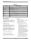
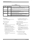
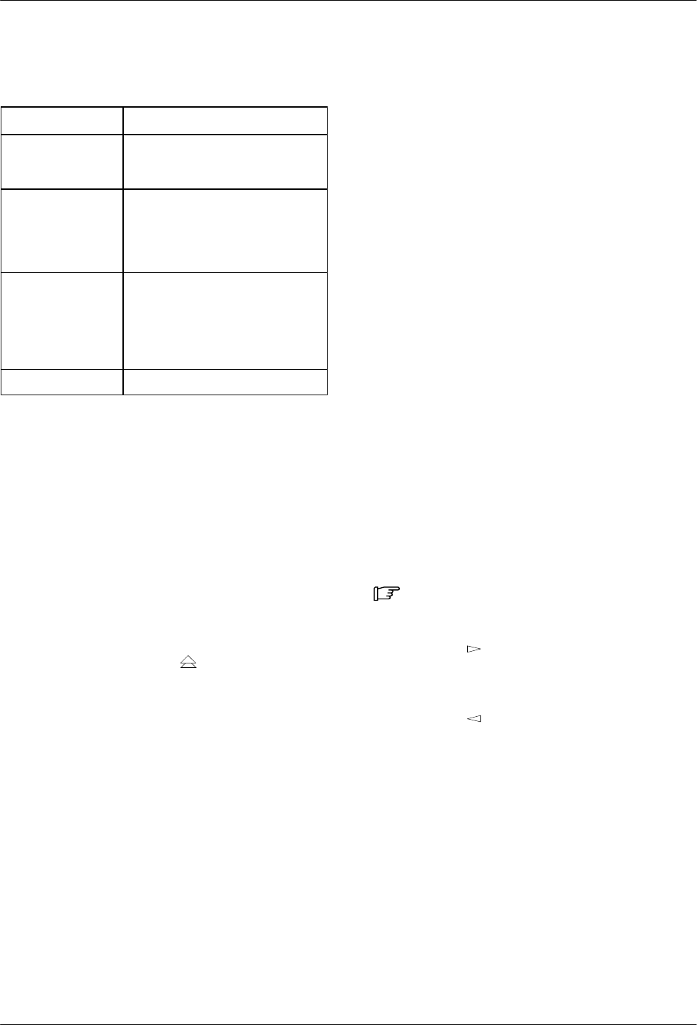
Table 4-5
Bit Error Rate Test Results
Results Information Displayed
Time: Running test timer. (The Clr
selection resets the timer to
0:00:00.)
Tot Error: Running count of bits in
error; Max, if the maximum error
count has been reached, which
is 64000. (The Clr selection
resets the counter to 0.)
Err Secs: Running count of errored
seconds. Errored second is at
least one error is detected during
a 1-second time period. (The Clr
selection resets the counter to
0.)
Run on:port
nn
Port selected for testing.
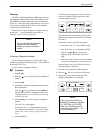
Lamp Test
The Lamp Test is a test of the status indicators (LEDs)
and liquid crystal display (LCD) on the DSU’s control
panel (both models). Any indicator that does not flash is
not functional.
Note that if all LEDs are functioning, all the indicators
on the Model 3550 DCP are flashing steadily. In a
COMSPHERE 3000 Series Carrier, the indicators on the
SDCP remain ON. The LCD on the DCP or SDCP
alternately flashes solid blocks, moving from position to
position on the display until the test is aborted.
Pressing any key except the
key will stop the LCD
portion of the Lamp Test and return you to the DSU Test
menu so you can abort the test. Once aborted, the LCD
and LEDs stop flashing.
Configuration Branch
The Configuration (Confg) branch allows you to
configure or customize the DSU and its equipment (DBM
or TDM/Flex) to fit your site’s requirements, to enter and
change telephone numbers (if a DBM is installed), and to
specify the mode for viewing or editing configuration
options.
The 3550 Series DSUs have two special features that
simplify configuration of your DSU: Menu mode and the
preset (factory-set) unit configurations to fit typical DSU
applications.
It is recommended that you set the Menu mode before
you select an application configuration, or access option
sets.
Selecting Menu Mode
By selecting Menu from the Configuration Options
(Opts) branch, you can
• View and configure options in each option set, or
• View and edit only those options that are more
likely to change.
This feature saves time and simplifies customization of
your DSU’s configuration. Appendix B, Configuration
Worksheets, summarizes the unit’s configuration options
for each Menu mode selection.
Procedure
1. Select Local (F1) for the local DSU.
2. Press the
key until Confg (Configuration
branch) is displayed.
3. Select the function key directly below Opts (F3).
4. Press the
key to display Menu.
5. Select Menu (F1). Full Mode appears on the first
line of the LCD.