


Operating the DSU
4-193550-A2-GB20-10 February 1995
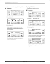
6. Select Save (F2).
The DSU displays the address assigned along with
a Command Complete message.
If an error was made in entering the address:
Procedure
1. Press the
key to return to the Configure
screen.
2. Re-select Addr, and re-edit the address.
3. Select Save again.
Control Branch
The Control (Ctrl) branch allows you to enable or
disable the DSU’s transmitter, as well as the DBM’s or
port’s, and to display or change the status of the general
purpose external DTE leads. A DBM can be disabled if it
is addressed from the Remote branch.
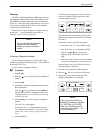
Transmitter Control
The Transmitter Control (TxCtl) selection allows you
to enable or disable the DSU’s, DBM’s, or port’s
transmitter (DDS core).
When the DSU transmitter is disabled, the following is
possible:
• When a DSU is disabled, it responds to tests.
Aborting a test clears the test but the unit remains
disabled.
• A DSU in test clears the test when a disable (or
enable) command is received.
• If an enable command is executed to a control from
the NMS or the local DCP, all disabled tributaries
are enabled; all tributaries in test are restored to
Data mode.
When the local DBM is disabled, the DBM does not
originate or answer any calls until enabled.
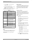
LEDs
The LEDs selection is only available from the Local
branch. This selection allows you to monitor the port at
any given time. When selected, the port’s lead activity is
reflected in the DCP circuit designation status indicators
(TXD, RXD, etc.) on the faceplate of the Model 3551
DSU, or on the DCP of the Model 3550 DSU.
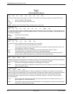
External Leads
The External Leads (ExtL) selection allows you to
display the state of four general-purpose leads on the
EIA-232-D/V.24 Port 1 interface: Pins 12 and 13 for
output (control leads) and Pins 19 and 23 for input (alarm
leads).
When the configuration option Ext Leads (External
Leads) is set to ExtLd, you can change the state of the two
output leads from the DCP or a 6700 Series NMS. When
CCN by EL (CCN by External Leads) is enabled, the
control DSU reports changes in the four leads to the 6700
Series NMS as part of its health and status poll response.
Table 4-7 describes the meaning of the state of each
input or output lead.
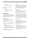
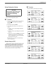
Displaying External Leads
The Display (Displ) selection allows you to view the
external lead states. When Display is selected, the
External Leads status report appears showing the current
status of the general-purpose external leads on the
EIA-232-D/V.24 interface.
Changing External Leads
The Change (Chang) selection allows you to change
the state of the two output leads (for example, to change a
lead to signal a console operator or to reset a remote
computer). Leads can be changed from the NMS.
After the leads are set, press the F2 key to save the
leads in the specified state.