


RC840 400-276-000-C 17/1/07 1/2
The RC840 Electric Heating Relay is designed to control a line
voltage resistive load from a 24 V control signal.
The RC840 operates silently and can be installed in bedrooms, living
rooms, or any other occupied area without disturbing occupants. On
a call for heat, the relay is immediately activated; there is no delay.
This increases temperature control and comfort.
NOTE: Not recommended for fast-cycling modulated regulation. For fast-
cycling heating equipment, It is recommended to use the RT850 or RT850T
(integrated 24 V transformer) Solid State Relay.
I
The RC840 must be installed in an area where the temperature is
between -4°F and 140°F (-20°C and 60°C).
The RC840 can be installed on the side of an electrical box or a
distribution panel or inside the wiring compartment of an electric
baseboard.
All wiring must comply with national and local electrical code
regulations.
Installation should be carried out by an electrician.
Disconnect power supply before installing the relay to prevent
electrical shock.
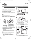
n Secure relay to the mounting surface using the two mounting
brackets. Use the supplied lock nut to secure the relay to the
junction box.
o Wire the relay and connect according to typical wiring diagrams
(refer to figures 1, 2 and 3).
p Once mounting and wiring have been completed, return power
to the heating system and test the installation.
q Increase the thermostat temperature to activate the relay. Allow
system operation long enough to proof installation. Once
installation has been proofed, set temperature to normal
setpoint.
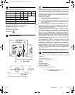
Figure 1 : Connection to a 2-wire low voltage thermostat using a 24 V
external transformer
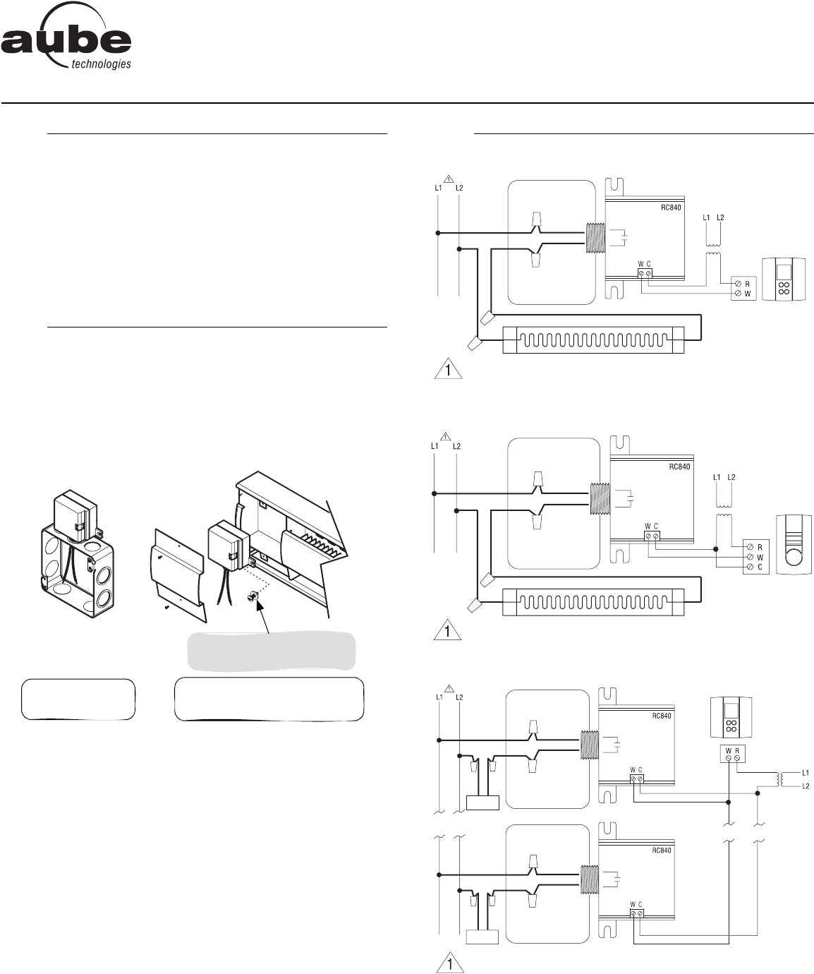
Figure 2 : Connection to a 3-wire low voltage thermostat using a 24 V
external transformer
Figure 3 : Connection to a 2-wire low voltage thermostat using a 24 V
external transformer and multiple relays
n
Application
1.
o
Installation
2.
On the side of
an electrical box
Inside the wiring compartment
of a baseboard
For proper installation, use
a screw and a washer.
p
Typical Wiring Diagrams
3.
You must provide an overload protection and disconnect as required.
External 24V
transformer
Low-voltage
2-wire
thermostat
Load
Junction box
Black
Red
You must provide an overload protection and disconnect as required.
External 24V
transformer
Low-voltage
3-wire
thermostat
Load
Junction box
Red
Black
You must provide an overload protection and disconnect as required.
Transformer VA output = RC840 Quantity x 1.2 VA
External 24V
transformer
Low-voltage
2-wire
thermostat
Load
Load
Junction box
Junction box
Red
Black
Red
Black
RC840
Installation Guide
On/Off Switching Electric Heating Relay
400-276-000-C (RC840) ENG.fm Page 1 Wednesday, January 17, 2007 3:48 PM