28 EVR1500 Installer/User Guide
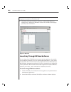
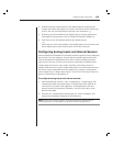
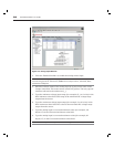
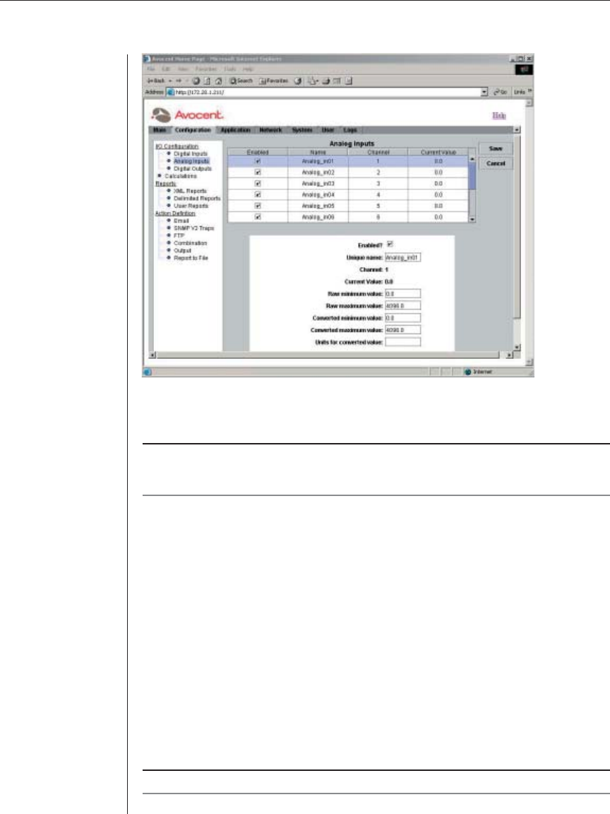
Figure 3.10: Analog Inputs Window
3. Click the Enabled checkbox to enable the analog sensor input.
NOTE: An enabled analog input will display in the Main tab window and will be available for use
in the following operations: Calculations, SNMP actions, Output actions, Thresholds, Rules,
Timed Rules and Reports.
4. If desired, edit the name of the analog input by typing a new name in the
Unique name fi eld. The name cannot contain any spaces. The only special
character allowed is the underscore (_).
5. Type the minimum voltage input range (for example, Ø, 1 or 2 volts) in the
Raw minimum value fi eld. This range is the minimum DC voltage range
output from the sensor.
6. Type the maximum voltage input range (for example, 5 or 10 volts) in the
Raw maximum value fi eld. This value is the maximum DC voltage range
output from the sensor.
7. Type the analog input’s converted minimum value (for example, -40
degrees F) in the Converted minimum value fi eld.
8. Type the analog input’s converted maximum value (for example, 85
degrees F) in the Converted maximum value fi eld.
NOTE: Values for steps 5 to 8 are provided with the analog sensor documentation.


