


Barracuda
®
ATA III
Family Installation Guide
ST340824A, ST330620A, ST320414A, ST315310A, ST310215A
The Easiest Way to Install Your Drive
DiscWizard is Seagate’s exclusive Windows program that is included with
your drive for easy drive installation. You can use this software if you have a
bootable hard drive in your computer and are running
Windows Me,
Windows 98 or Windows 95.
Download the software from our Web site at
www.seagate.com.
Run DiscWizard
before
installing your drive for customized step-by-step
instructions for your system.
To run DiscWizard:
Download the software from www.seagate.com, and follow the online
instructions to complete the installation.
If you cannot run DiscWizard, follow the instructions on this installation
sheet to install and configure your drive.
What You Need
• A Phillips screwdriver and four 6-32 UNC drive mounting screws
• A standard 40-pin ATA interface cable,
or
an 80-conductor cable to run
Ultra ATA 100 (max length: 18 inches)
• An unused drive power cable for your new drive
• A version of Windows with FAT32 file system for drives over 32 Gbytes
Ultra ATA/100 Requirements
The drive can be configured to support a default maximum transfer rate.
This drive can support transfer rates up to 100 Mbytes per second
(UDMA 5) in Ultra ATA/100 mode. Using a software utility, you can set the
default transfer rate to the best capability of your system. For your drive to
run in this mode, you need the following:
• A computer that supports UDMA mode 5
• A 40-pin 80-conductor cable (available from your dealer)
• A software utility to confirm and activate Ultra ATA/100. Seagate
®
provides
a utility called UATA100.exe. You can download the latest version from our
Web site at
www.seagate.com.
• Windows Me or Windows 98 operating system: either supports Ultra ATA
100.
Handling Precautions
Disc drives are extremely fragile.
Do not
drop or jar the drive.
Keep the drive in the protective SeaShell container until you are
ready to install it. This minimizes handling damage.
The drive has a protective cover called SeaShield
®
. Do not remove
this permanent cover—it protects the drive from electrostatic
discharge (ESD) and minor impact damage.
Protect your drive from static discharge by wearing a grounded wrist
strap throughout the installation process.
Always handle the drive by the edges or frame.
Do not apply pressure or attach labels to the circuit board or the
top of the drive.
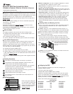
Setting the Jumpers
Refer to the jumper settings on
your drive label to configure the
drive for your system. Jumper
settings can also be accessed
online from our Web site at
www.seagate.com
• Master or single-drive: The drive is shipped configured for a master
or a single-drive with a jumper set on pins 7 and 8.
• Drive is slave: To configure the drive as a slave, or second drive on
the cable, remove all the jumpers.
• Master with non-ATA compatible slave: Use this setting if the slave
drive is not recognized. Configure the master drive with a jumper set on
pins 5 and 6 and pins 7 and 8 to enable this option.
• Cable-select option: Computers that use cable-select determine the
master and slave drives by selecting or deselecting pin 28, CSEL, on
the interface bus. To enable cable select, set a jumper on pins 5 and 6.
• Alternate capacity jumper: Drives with a 40-Gbyte capacity are
limited to 32 Gbytes. This jumper is used to provide a solution to
specific legacy BIOS problems. When using the alternate capacity
jumper, Disk Manager software is required to achieve the drive’s full
capacity.
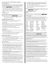
Attaching Cables and Mounting the Drive
1. Attach one end of the drive interface cable to the interface connector
on your computer’s motherboard
(see your computer manual for
connector locations).
!
Caution. Align pin 1 on the motherboard connector with pin 1 on
your drive connector. Pin 1 is marked by a stripe on one side of the cable.
2. Attach the interface connector and the power connector to the drive.
Note. You can mount the drive in any orientation. Usually it is mounted
with the circuit board down.
3. Secure the drive in the computer using four 6-32 UNC mounting
screws in either the side-mounting or bottom-mounting holes. Insert
the screws no more than 0.20 inch (5.08 mm) into the bottom-mounting
holes and no more than 0.14 inch (3.55 mm) into the side-mounting holes.
!
Caution. Do not overtighten the screws or use metric screws. This
may damage the drive.
Configuring the BIOS
For your computer to recognize your new drive, configure your
computer’s BIOS as follows:
1. Run the system setup program.
2. Enable LBA mode and UDMA mode, if available.
3. Select the auto-detect option. If necessary, refer to the drive param-
eters on your drive label to configure the drive for your system. BIOS
settings can also be accessed at
www.seagate.com. To access the full
capacity of the drive, use LBA mode or use Disk Manager.
4. Save and exit the system setup program.
BIOS Settings
Drive Model Formatted Gbytes Total Sectors*
ST340824A 40.0 78,165,360
ST330620A 30.0 58,633,344
ST320414A 20.0 39,102,336
ST315310A 15.3 29,888,820
ST310215A 10.2 19,925,880
*One sector equals 512 bytes.
Publication Number: 21200270-001, Rev. A
Pin 1
Interface
connector
Power
connector
Computer
Motherboard
Pin 1
Master
Slave
Note. If you are using a 40-pin 80-conductor
cable, attach the
blue
connector to the
motherboard, the
black
connector to the
master drive, and the
grey
connector
to the slave.
Options jumper block
Circuit Board
2
684
1753
Drive is slave
Master or single drive
Cable select
Master with non ATA-
compatible slave
Limits drive capacity
to 32 Gbytes