


EIR510 Series-5107qsg
International Headquarters: 707 Dayton Road PO Box 1040 Ottawa, IL 61350 USA
815-433-5100 Fax 433-5104 www.bb-elec.com
orders@bb-elec.com support@bb-elec.com
European Headquarters: Westlink Commercial Park Oranmore Co. Galway Ireland
+353 91 792444 Fax +353 91 792445
www.bb-europe
.com orders@bb-europe.com support@bb-europe.com
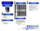
Items Included
1
2
Default Settings
3
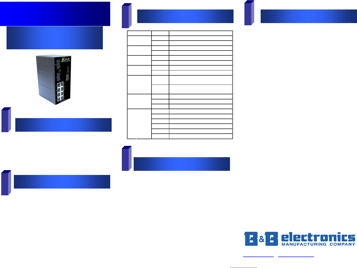
LED Chart
4
Hardware Installation
Log into the Switch
5
o Ethernet Switch
o Console Cable (RS-232 RJ-45 to DB-9)
o CD with Support Manual
o This Quick Start Guide
o Panel Mount Bracket
o IP Address: 192.168.16.1
o Subnet Mask: 255.255.255.0
o Gateway: 192.168.16.254
o User Name: root, Password: root
LED Status Meaning
Green The Switch is powered on
PWR
Off The Switch is powered off
Green Power Source 1 is available
PWR1
Off Power Source 1 is unavailable
Green Power Source 2 is available
PWR2
Off Power source 2 is unavailable
Orange A power or port failure has occurred
Fault
Off Normal Operation
Green
The Switch is the master of a redundant
ring (X-Ring)
R.M
Off
The Switch is not the master of a
redundant ring.
Green The port is linked
Blinking Data is being transmitted or received
LINK/ACT
(P9/P10)
Off Not connected to the network
Top Green Connected to the network
Top Blinking Transmitting or receiving
Top Off Not connected to the network
Bottom Orange Operating at full-duplex
Bottom Blinking Collision
P
1-8
Bottom Off Half-duplex or not connected
o Record the switch’s MAC Address in the space
provided. Provide the MAC Address to your Network
Administrator. The Network Administrator will
provide an IP Address, Subnet Mask and Gateway.
o Select a mounting location and install with the attached
DIN rail clip or included panel mount kit.
o Connect power to the switch
o 24 to 48 VDC
o Redundant inputs are available with fault
contacts.
o These instructions are for Web based management.
Refer to the User’s Manual for instructions concerning
console management.
o Connect a stand alone PC to a port on the switch.
Change the PC’s network IP Address to allow it to
connect to the switch (ex: 192.168.16.2). Use the
default subnet mask and gateway.
o Launch the PC’s web browser and navigate to the
switch by typing the switch’s IP address in the browser
address window.
o Navigate the web page by expanding the folders on the
left side of the web page.
Quick Start Guide
Elinx Managed Ethernet Switch
EIR510 Series