


EIR608 Series-5107qsg
International Headquarters: 707 Dayton Road PO Box 1040 Ottawa, IL 61350 USA
815-433-5100 Fax 433-5104 www.bb-elec.com
orders@bb-elec.com support@bb-elec.com
European Headquarters: Westlink Commercial Park Oranmore Co. Galway Ireland
+353 91 792444 Fax +353 91 792445
www.bb-europe
.com orders@bb-europe.com support@bb-europe.com
Quick Start Guide
Elinx Managed Ethernet Switch
EIR608 Series
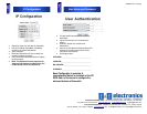
Items Included
1
2
Default Settings
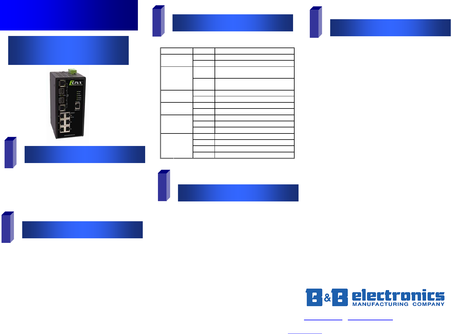
LED Chart
4
Hardware Installation
Log into the Switch
5
3
o Ethernet Switch
o Console Cable (RS-232 RJ-45 to DB-9)
o CD with Support Manual
o This Quick Start Guide
o Panel Mount Bracket
o IP Address: 192.168.16.1
o Subnet Mask: 255.255.2555.0
o Gateway: 192.168.16.254
o Username: root Password: root
o Record the switch’s MAC Address. The
MAC Address is printed on the product label. Provide
the MAC Address to your Network Administrator.
The Network Administrator should provide an IP
Address, Subnet Mask, and Gateway.
o Select a mounting location and install with the attached
DIN rail clip or included panel mount kit.
o Connect power to the switch
o 12 to 48 VDC
o Redundant DC input is available with fault
contacts.
NOTE: The installation of an SFP Module disables
the associated RJ-45 Port.
o These instructions are for Web based management.
Refer to the User’s Manual for instructions concerning
console management.
o Connect a stand alone PC to a port on the switch.
Change the PC’s network IP Address to allow it to
connect to the switch (ex: 192.168.16.2). Use the
default subnet mask and gateway.
o Launch the PC’s web browser and navigate to the
switch by typing the switch’s IP address in the browser
address window.
o Navigate the web page by expanding the folders on the
left side of the web page.
LED Status Meaning
Green The Switch is powered on
PWR
Off The Switch is powered off
Green
The Switch is the master of a redundant
ring (X-Ring)
R.M
Off
The Switch is not the master of a
redundant ring.
Green Power Source 1 is available
PWR1
Off Power Source 1 is unavailable
Green Power Source 2 is available
PWR2
Off Power source 2 is unavailable
Green SFP Port is linked
Blinking Data is being transmitted or received
LINK/ACT
(P7/P8 SFP)
Off Not connected to the network
Top Green Connected to the network
Top Blinking Transmitting or receiving
Bottom Off Not connected or operating at 10/100
P1-8
Bottom Green Operating at 1000M