


5
EUROPOWER EP1500/EP2500
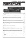
2. CONTROL ELEMENTS
+ If the unit is damaged, please do NOT return it to
BEHRINGER, but notify your dealer and the shipping
company immediately. Otherwise, claims for damage
or replacement may not be granted.
Please make sure the unit is provided with sufficient ventilation,
and never place your EUROPOWER amp on top of other heat-
emanating equipment or in the vicinity of a heater to avoid the risk
of overheating.
The mains connection is made via the enclosed power cord
and a standard IEC receptacle. It meets all international safety
certification requirements.
+ Please make sure that all units have a proper ground
connection. For your own safety, never remove or
disable the ground conductor from the unit or the
AC power cord.
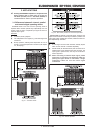
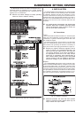
These are the balanced XLR inputs (channels 1 and 2).
These are the stereo 1/4" TRS inputs (channels 1 and 2).
They can also be used with unbalanced plugs.
These are the MODE switches, used to alter the operating
modes as well as to set the limiters and high-pass filters
(see chapter 2.3).
The units fan is located here. Fan speed adjusts
automatically to assure trouble-free operation.
+ To prevent faulty operation, please assure that
the unit is kept at a distance from other appliances
emanating heat.
ATTENTION!
+ We would like to bring your attention to the fact
that extremely loud sound levels may damage your
hearing as well as your loudspeakers. Please lower
both GAIN controls leftwards before powering up
the unit. Be sure to keep the volume at an
appropriate level.
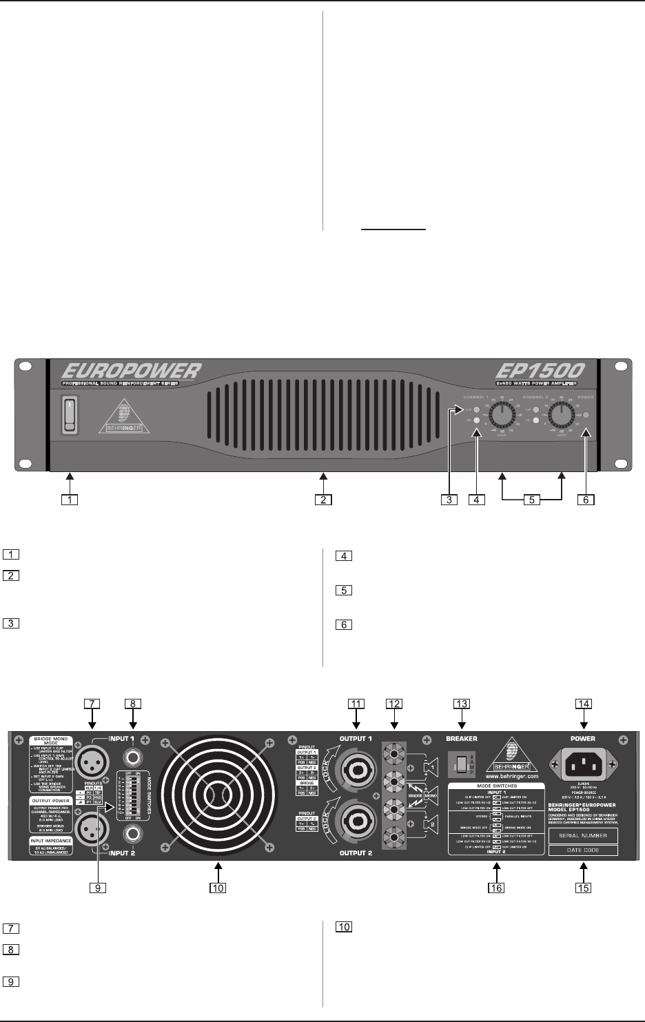
2. CONTROL ELEMENTS
Since control elements of both the EP1500 and the EP2500 are identical, we have used the EP1500 as the model represented in the
illustrations to assure simplicity.
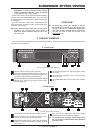
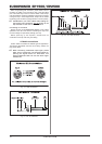
2.1 Front panel
Fig. 2.1: Front panel control elements
The main switch is used to power up the amp.
Ventilation openings are located at the front of the unit, so
that hot air is prevented from being trapped inside the unit,
thus causing faulty operation or even damage.
The CLIP LED lights up when the signal is distorted. Should
distortion occur, reduce the input level, so that the CLIP
LED stops lighting up.
The SIGNAL LED lights up as long as a signal is present
at the input.
The GAIN control (channels 1 and 2) is used for setting
up the input gain.
The POWER LED lights up as soon as the unit is powered
up.
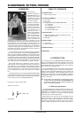
2.2 Rear panel
Fig. 2.2: Rear panel control elements