


6
EUROPOWER EP1500/EP2500
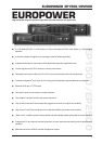
2. CONTROL ELEMENTS
These are the Speakon
®
outputs (channels 1 and 2). When
running the unit in mono-bridged mode (see chapter 2.3.5),
please use the channel 1 output exclusively. For further
information on Speakon
®
connectors please refer to
chapter 4.1.
These are the output terminals (channels 1 and 2). When
running in mono, please make sure to use both middle
connectors to connect your loudspeaker.
BREAKER (automated fuse). After eliminating the cause
of faulty operation, simply depress the BREAKER and
power up the unit again. The BREAKER acts in place of
common discardable fuses.
+ Attention: Before engaging the BREAKER switch,
you should power down the unit (POWER switch
set to OFF)!
Power is supplied via an IEC connector. The matching
cable is provided with the unit.
SERIAL NUMBER of your EUROPOWER. Please take the
time and send us the completely filled out warranty card
within 14 days of the date of purchase. You may also
register online at www.behringer.com.
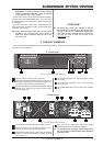
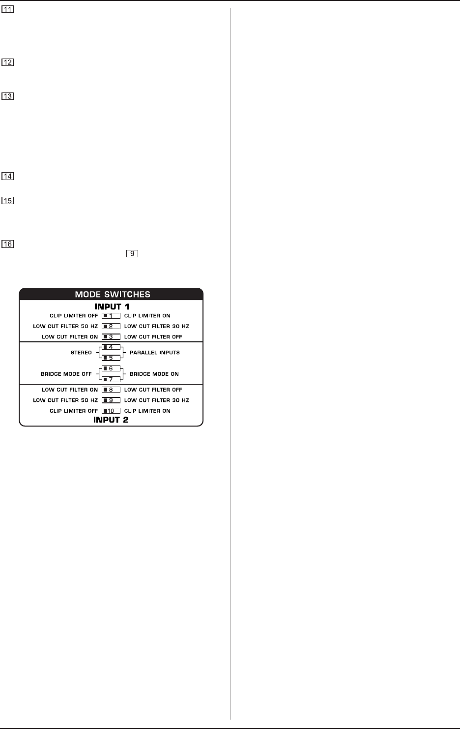
Here you can find a detailed overview of the individual
MODE SWITCHES functions ( ).
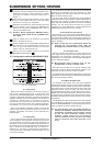
2.3 Configuration switches (MODE SWITCHES)
Fig. 2.3: DIP-switches
2.3.1 Clip limiter
When the input signal connected to your amp is too high, you
end up with a distorted output signal. To prevent this, both
channels of your EUROPOWER feature a clip limiter that can be
engaged or disengaged selectively. The limiters automatically
recognize distortion and lower amplification until distortion is
reduced to a tolerable level. To preserve the dynamic
characteristics of the signal when low distortion levels are
occurring, the clip limiters function with moderate suppression.
Use switches 1 (ch. 1) and 10 (ch. 2) to activate the clip limiters.
When using broadband loudspeaker systems, the clip limiter
reduces high frequency distortions which occur when an
amplifier is overloaded. The drivers are thus protected from
being damaged.
2.3.2 Input filter
The LF (high-pass) filter removes frequencies below 30 and
50 Hz respectively. The reproduction of the signals bass portion
is thus optimized, since ultra-low, distracting frequencies are
eliminated, and more power is available for the reproduction of
the wanted segment of the signal. Engaging and disengaging the
filters is done by using the switches 3 (ch. 1) and 8 (ch. 2).
Switches 2 (ch. 1) and 9 (ch. 2) determine the cut-off frequency.
As long as the filter is disengaged, frequencies below 5 Hz are
cut to prevent damage.
You should set up the filters so they best suit the frequency
response of your speakers, since some speakers (e.g. bass
reflex speakers) are particularly sensitive to over-excursion
below the listed frequency range.
The 50 Hz filter should be engaged when using broadband
speakers because the filter provides a moderate amplification in
the 100-Hz range, resulting in a fuller sound. The 30 Hz filter is
ideally suited for subwoofer operation as well as for broadband
cabinets. The Off setting should be used only for special
applications (e.g. studio applications), in which recognizing and
subsequently removing infra-sound is important.
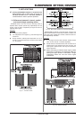
2.3.3 2-channel mode (stereo)
Both channels of your amp function independently from one
another in this operating mode, and each has its own input signal.
Two independent speakers are connected at the outputs. To
activate this operating mode, please set the MODE SWITCHES 4
and 5 to STEREO.
+ When running the unit in two-channel mode, the
switches for mono-bridged mode must be
disengaged (dip switches 6 and 7 in left position).
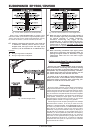
2.3.4 Parallel mode
Running in parallel mode enables you to feed a signal via one
of the inputs into both outputs. Each channel drives its own
loudspeaker with independent amplification, filter and limit
characteristics. To link the inputs, set the MODE SWITCHES 4
and 5 to PARALLEL INPUTS.
+ Mono-bridged mode switches must be dis-
engaged when running in parallel mode.
With inputs set to parallel, you can use the remaining input
connectors to feed the signal into additional amplifiers. This
means that the channel 2 inputs function as outputs.
The parallel mode is well-suited for applications in which driving
two speakers with the same signal but with separate amplification,
filter and limiter settings is desired.
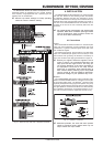
2.3.5 Mono-bridged mode
This operating mode enables you to add up the respective
voltage of both channels and use it to drive a single loudspeaker.
The voltage is therefore doubled, the peak power is quadrupled,
and program power is roughly three times as high as that of the
individual channels. The input, output, gain, filter and limiter
controls belonging to channel 1 are used when running in mono-
bridged mode. The controls belonging to channel 2 are not used.
To prevent signal cancellation due to internal phase inversion,
the GAIN control belonging to channel 2 must be turned to its left-
most position.
Use this operating mode to route the power from both channels
to a single 8-Ohm or 4-Ohm load. To do so, set up the switches
6 and 7 to BRIDGE MODE ON. To use the binding posts as your
output, you MUST use the two middle posts only.
+ The mono-bridged mode puts added demands on
amplifier and speakers. Excessive distortion may
occasionally completely mute the amps outputs
as well as cause permanent damage to the
speakers. Please assure that your speakers
(minimal impedance 4 Ohms) as well as the cables
used can handle the extra power generated in this
mode.