


OmniView
™
KVM Switch
PRO2 PS/2
Quick Installation Guide
Switch KVM OmniView
™
PRO2 PS/2
Guide d’installation rapide
OmniView
™
KVM-Masterswitch
PRO2 PS/2
Installationsanleitung
PS/2
PS/2
PS/2
Introduction
This sheet will guide you through the basic steps needed to install the PRO2 PS/2
Series KVM Switch (the PRO2 PS/2). If you have any problems during installation,
please refer to the PRO2 PS/2 User Manual.
The following items are needed to install the PRO2 PS/2:
• OmniView PRO2 PS/2 Series KVM Switch
• One (each) PS/2 keyboard, monitor, and mouse
• One KVM cable per computer installed
• One 12-volt DC, 1-A power supply unit
Recommended Cable Kits:
F3X1105BXX PS/2 Style
F1D108-CBL Daisy-Chain Cable
(-XX denotes the length in feet)
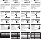
Step 1:
Connecting the Keyboard, Video, and Mouse to the
Console Ports on the PRO2 PS/2
1. Power down all computers.
2. Connect the PS/2-type keyboard
and mouse to the Console ports
located on the back panel of the
PRO2 PS/2.
3. Connect the video cable that is
attached to the monitor, to the
Console video port located on the
back panel of the PRO2 PS/2.
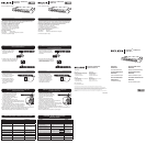
1. Connect the included 12-volt DC, 1-A power supply unit into an available power
outlet.
2. Attach the barrel plug
into the power jack
located on the rear of the
PRO2 PS/2
to power the unit.
The LEDs should illuminate.
VGA
VG
A
VGA
VGA
VGA
VGA
VGA
VGA
VGA
08
08
07
07
06 06
06 05
05
04
04 03
03
02
02
01
01
Step 2:
Powering up the PRO2 PS/2
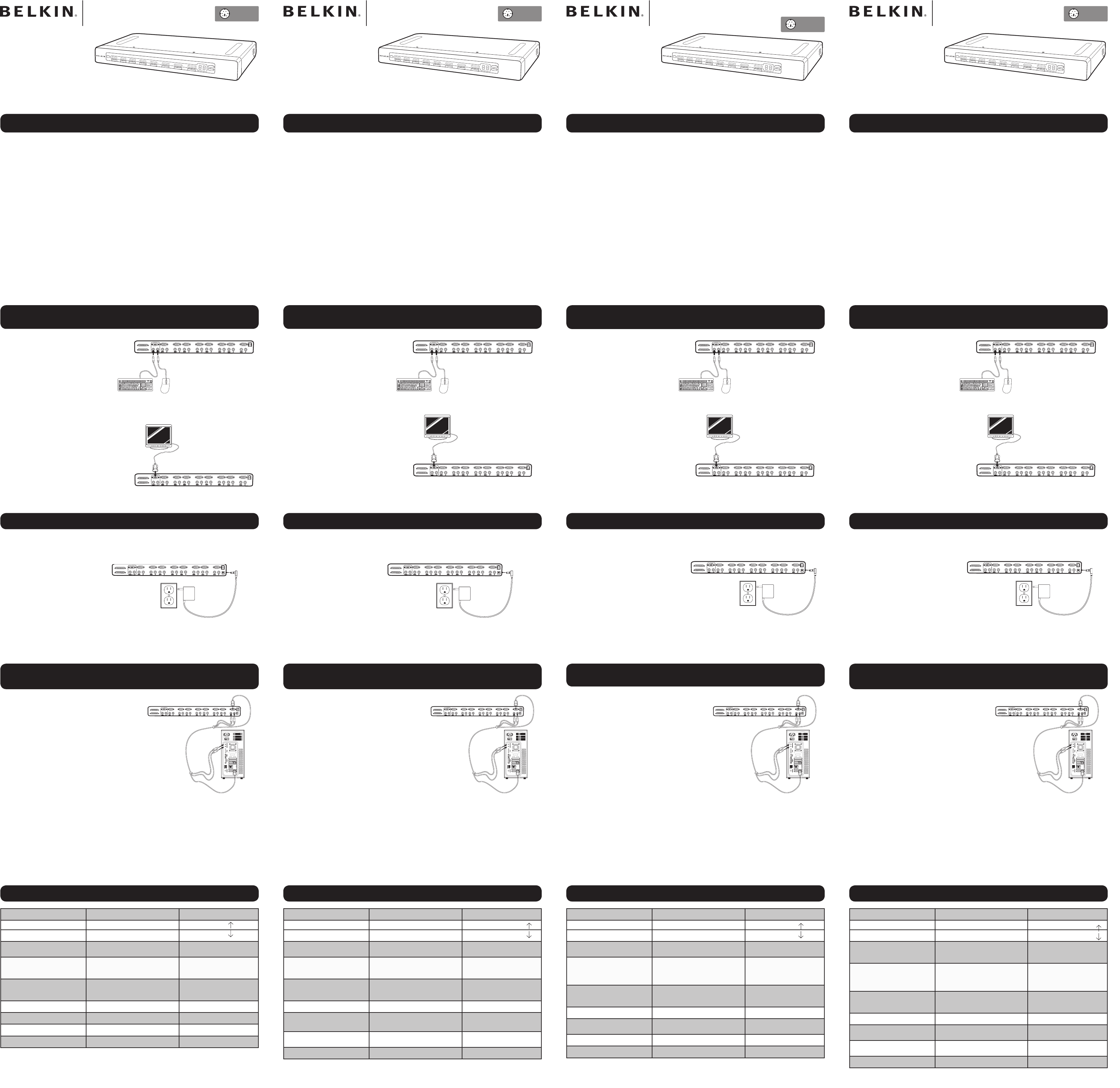
Step 3:
Connecting Computers to the PRO2 PS/2 (Video and PS/2
Connection)
1. Using an OmniView KVM Cable*,
connect the male end of the VGA
cable to the VGA port on the first
computer. Connect the female end
to the VGA port on the back of the
PRO2 PS/2 for CPU1.
2. Connect one end of the PS/2 key-
board KVM Cable* to the keyboard port on the com-
puter and the other end to the CPU1 keyboard port on
the back of the PRO2 PS/2.
3. Connect one end of the PS/2 mouse KVM cable* to the
mouse port on the computer and the other end to the
CPU1 mouse port on the back of the PRO2 PS/2.
Repeat steps 1 through 3 for each additional computer to be connected to the
PRO2 PS/2, connecting them to the corresponding CPU ports on the back.
* Please refer to the first page for part numbers.
VGA
VG
A
VG
A
VG
A
VG
A
VG
A
VGA
VG
A
VG
A
08
08
07
07
06 06
06 05
05
04
04 03
03
02
02
01
01
Hot Key Commands – Quick Reference
Please refer to your User Manual for additional information.
Introduction
Ce document vous guidera à travers les étapes élémentaires nécessaires à
l'installation du switch KVM série PRO2 PS/2 (le PRO2 PS/2). Si vous rencontrez
des problèmes lors de l'installation, reportez-vous au manuel de l'utilisateur du
PRO2 PS/2.
Les éléments suivants sont nécessaires pour pouvoir installer le PRO2 PS/2 :
• Switch KVM OmniView série PRO2 PS/2
• Un clavier PS/2, un moniteur PS/2 et une souris PS/2
• Un câble KVM par ordinateur installé
• Un bloc d'alimentation c.c. 12 V, 1 A
Kits de câbles conseillés :
F3X1105BXX Type PS/2
F1D108-CBL Câble de raccordement en série
(-XX indique la longueur en pieds)
Etape 1:
Branchement du clavier, du moniteur et de la souris sur les
ports de la console du PRO2 PS/2
1. Mettez tous les ordinateurs hors
tension.
2. Branchez le clavier et la souris
PS/2 sur les ports de la console
à l'arrière du PRO2 PS/2.
3. Branchez le câble vidéo relié au
moniteur sur le port vidéo de la
console situé à l'arrière du PRO2
PS/2.
1. Branchez le bloc d'alimentation c.c. 12 V, 1 A fourni sur une prise secteur libre.
2. Insérez la prise dans la
fiche d'alimentation à
l'arrière du PRO2 PS/2
pour alimenter l'unité.
Les voyants devraient
s'allumer.
Etape 2:
Démarrage du PRO2 PS/2
Etape 3:
Branchement des ordinateurs sur le PRO2 PS/2 (connexion
vidéo et PS/2)
1. Branchez l'extrémité mâle du câble
VGA KVM OmniView* sur le port
VGA du premier ordinateur. Branchez
l'extrémité femelle sur le port VGA à
l'arrière du PRO2 PS/2 (CPU1).
2. Branchez une extrémité du câble
KVM clavier PS/2* sur le port clavier
de l'ordinateur et l'autre extrémité sur
le port clavier CPU 1 à l'arrière du PRO2 PS/2.
3. Branchez une extrémité d'un câble KVM souris PS/2*
sur le port souris de l'ordinateur et l'autre extrémité sur
le port souris CPU 1 à l'arrière du PRO2 PS/2.
Répétez les étapes 1 à 3 pour chaque ordinateur supplé-
mentaire que vous connectez au PRO2 PS/2. Branchez-les
sur les ports CPU correspondants à l'arrière de l'unité.
* Reportez-vous à la première page pour connaître les références.
Raccourcis clavier – Référence rapide
Einführung
Diese Kurzanleitung führt Sie durch die wesentlichen Schritte der Installation des
PRO2 PS/2-Masterswitch. Wenn es bei der Installation zu Problemen kommt,
finden Sie weitere Informationen im PRO2 PS/2-Benutzerhandbuch.
Zur Installation des PRO2 PS/2-Masterswitch wird Folgendes benötigt:
• OmniView PRO2 PS/2-Serie Masterswitch
• Eine PS/2-Tastatur, ein Bildschirm und eine PS/2-Maus.
• Ein Masterswitch-Kabel für jeden installierten Computer
• Ein Netzteil (12 V; 1 A)
Empfohlene Kabelsätze:
F3X1105BXX PS/2-Ausführung
F1D108-CBL Kaskadierungskabel
(XX = Länge gemessen in Fuß)
Schritt 1:
Anschließen der Tastatur, des Bildschirms und der Maus an die
Konsolenschnittstellen am PRO2 PS/2-Masterswitch
1. Schalten Sie alle Computer ab.
2. Verbinden Sie die PS/2-Tastatur
und das PS/2-Mauskabel mit
den Konsolenschnittstellen an
der Rückseite des PRO2 PS/2-
Masterswitch.
3. Verbinden Sie das Monitorkabel
des Bildschirms mit der
Konsolen-Monitorschnittstelle an
der Rückseite des PRO2 PS/2-
Masterswitch.
1. Schließen Sie das enthaltene Netzteil (12 V; 1 A) an eine freie Steckdose an.
2. Stecken Sie den runden
Stecker in den Netzanschluss
an der Rückseite des PRO2
PS/2-Masterswitch, um ihn
mit dem Netz zu verbinden.
Jetzt müssten die LEDs
aufleuchten.
Schritt 2:
Einschalten des PRO2 PS/2-Masterswitch
Schritt 3:
Anschließen von Computern an den PRO2 PS/2-
Masterswitch (Bildschirm- und PS/2-Anschluss)
1. Verbinden Sie ein OmniView
Masterswitch-Kabel* mit dem Stecker
des VGA-Kabels und mit der VGA-
Schnittstelle des ersten Computers.
Verbinden Sie die Buchse der VGA-
Schnittstelle mit der Schnittstelle "CPU1"
an der Rückseite des PRO2 PS/2-
Masterswitch.
2. Verbinden Sie das PS/2-Masterswitch-Tastaturkabel* mit
der Tastaturschnittstelle des Computers und der CPU1
Tastaturschnittstelle an der Rückseite des PRO2 PS/2-
Masterswitch.
3. Verbinden Sie das PS/2-Masterswitch-Mauskabel* mit
der Mausschnittstelle des Computers und der CPU1
Mausschnittstelle an der Rückseite des PRO2 PS/2-
Masterswitch.
Wiederholen Sie die Schritte 1 bis 3 für jeden weiteren Computer, den Sie an den PRO2
PS/2-Masterswitch anschließen möchten, und verwenden Sie hierzu die entsprechenden
Computerschnittstellen ("CPU") an der Rückseite.
* Auf der ersten Seite finden Sie die Artikelnummern.
Tastaturbefehle: Kurzübersicht
Inleiding
Deze documentatie helpt u bij het nemen van de belangrijkste stappen voor het
installeren van de KVM-switch uit de PRO2 PS/2-Serie van Belkin (de PRO2 PS/2).
In geval van problemen tijdens de installatie, raden wij u aan de handleiding te
raadplegen.
Voor het installeren van de PRO2 PS/2 hebt u de volgende onderdelen nodig:
• OmniView KVM-switch uit de PRO2 PS/2-Serie
• Eén PS/2-toetsenbord, -monitor en -muis
• Een KVM-kabel per geïnstalleerde computer
• Een voedingsadapter (12 V DC, 1 A)
Aanbevolen kabelsets:
F3X1105BXX PS/2-uitvoering
F1D108-CBL Daisychainkabel
(-XX is lengte in voet)
Stap 1:
Toetsenbord, muis en monitor aansluiten op de
consolepoorten van de PRO2 PS/2
1. Schakel alle computers uit.
2. Sluit het toetsenbord en de muis
(beide van het type PS/2) aan
op de consolepoorten aan de
achterkant van de PRO2 PS/2.
3. Sluit de op de monitor aangesloten
videokabel aan op de console-vid-
eopoort aan de achterkant van de
PRO2 PS/2.
1. Sluit de meegeleverde 12V/1A-voedingsadapter aan op een stopcontact.
2. Sluit het andere uiteinde
van de voedingskabel aan
op de voedingsingang
aan de achterkant van de
PRO2 PS/2 om de switch
van stroom te voorzien.
LED’s zouden nu moeten
gaan branden.
Stap 2: De PRO2 PS/2 inschakelen
Stap 3:
Computers aansluiten op de PRO2 PS/2 (video- en PS/2-
aansluiting)
1. Maak gebruik van een OmniView
KVM-kabel* en sluit de male con-
nector van de VGA-kabel aan op de
VGA-poort van de eerste computer.
Sluit het female uiteinde aan op
de VGA-poort voor CPU 1, aan de
achterkant van de PRO2 PS/2.
2. Sluit het ene uiteinde van de KVM-
kabel voor het PS/2-toetsenbord aan op de toetsen-
bordpoort van de computer en het andere uiteinde op
de toetsenbordpoort voor CPU 1 aan de achterkant
van de PRO2 PS/2.
3. Sluit het ene uiteinde van de KVM-kabel* voor de PS/2-
muis aan op de muispoort van de computer en het ande-
re uiteinde op de muispoort voor CPU 1 aan de achterkant van de PRO2 PS/2.
Herhaal stap 1 t/m 3 voor elke computer die u op de daarvoor bestemde poorten
aan de achterkant van de PRO2 PS/2 aansluit.
*Artikelnummers treft u aan onder “Inleiding”.
Sneltoetsen - beknopt overzicht
Pour de plus amples informations, reportez-vous à votre manuel de l'utilisateur. Weitere Informationen hierzu finden Sie im Benutzerhandbuch.
Meer informatie vindt u in de bijbehorende handleiding.
OmniView
™
KVM-switch
PRO2 PS/2
Beknopte
installatiehandleiding
Fonctions Commandes
Changement de port Port ACTIF PRECEDENT Arrêt défil + Arrêt défil +
Port ACTIF SUIVANT Arrêt défil + Arrêt défil +
Commuter directement au PORT
(Configuration à un seul switch)
Y=01 à 16 Arrêt défil + Arrêt défil + Y
Changement de banc
(Par défaut, le premier port actif du
banc est sélectionné)
Passer au BANC PRECEDENT
Passer au BANC SUIVANT
Arrêt défil + Arrêt défil + PG prec
Arrêt défil + Arrêt défil + PG suiv
Permet de passer directement au
PORT Y sur le BANC X
F1DA104-OSD (X= 00 à 15)(Y= 01 à 04)
F1DA108-OSD (X=00 à 15)(Y= 01 à 08)
F1DA116-OSD (X= 00 à15)(Y= 01 à 16)
Arrêt défil + Arrêt défil + X + Y
Arrêt défil + Arrêt défil + X + Y
Arrêt défil + Arrêt défil + X + Y
Réintitialisation du menu OSD Arrêt défil + Arrêt défil + Del
Desactivation du son en mode «
AutoScan »
Arrêt défil + Arrêt défil + S
Activation de l'affichage à l'écran Arrêt défil + Arrêt défil +Barre
d'espacement
Activation du mode « AutoScan »
Arrêt défil + Arrêt défil + A
Funktionen Befehle
Schnittstellen wechseln Vorherige AKTIVE Schnittstelle Rollen + Rollen +
Nächste AKTIVE Schnittstelle Rollen + Rollen +
Direktschaltung zum PORT
(Einzelgerät-Konfiguration)
Y = 01 bis 16 Rollen + Rollen + Y
BANK wechseln
(Standardmäßig wird die erste
aktive Schnittstelle der BANK
ausgewählt)
Zurückschalten zur VORHERIGEN
BANK
Weiterschalten zur NÄCHSTEN BANK
Rollen + Rollen + Bild auf
Rollen + Rollen + Bild ab
Direktes Umschalten zu
Schnittstelle Y an BANK X
F1DA104-OSD (X= 00 bis15)(Y=01 bis 04)
F1DA108-OSD (X= 00 bis15)(Y=01 bis 08)
F1DA116-OSD (X= 00 bis15)(Y=01 bis16)
Rollen + Rollen + X + Y
Rollen + Rollen + X + Y
Rollen + Rollen + X + Y
Bildschirmmenüs zurücksetzen Rollen + Rollen + Del
Audioausgabe im AutoScan-
Modus deaktivieren
Rollen + Rollen + S
Bildschirmmenüs aktivieren
Rollen + Rollen + Leertaste
AutoScan-Modus aktivieren
Rollen + Rollen + A
Functies Commando's
Schakelen tussen poorten Vorige Actieve poort Scroll Lock + Scroll Lock +
Volgende Actieve poort Scroll Lock + Scroll Lock +
Rechtstreeks overschakelen naar
POORT
(Configuratie met één switch)
Y=01 tot 16 Scoll Lock + Scroll Lock + Y
Van BANK wisselen (Standaard
wordt de eerste actieve poort van
de BANK geselecteerd)
Overschakelen naar de VORIGE BANK
Overschakelen naar de VOLGENDE
BANK
Scroll Lock + Scroll Lock +
Page Up
Scroll Lock + Scroll Lock +
Page Down
Rechtstreeks overschakelen naar
POORT Y op BANK X
F1DA104-OSD (X=00 tot15)(Y=01 tot 04)
F1DA108-OSD (X=00 tot 15)(Y=01 tot 08)
F1DA116-OSD (X=00 tot 15)(Y=01 tot 16)
Scroll Lock + Scroll Lock + X + Y
Scroll Lock + Scroll Lock + X + Y
Scroll Lock + Scroll Lock + X + Y
Resetten On-Screen Display Scroll Lock + Scroll Lock + Del
Geluid uitschakelen in AutoScan-
modus
Scroll Lock + Scroll Lock + S
On-Screen Display activeren Scroll Lock + Scroll Lock +
spatiebalk
AutoScan-stand activeren Scroll Lock + Scroll Lock + A
Functions Commands
Switch Ports PREVIOUS ACTIVE port ScrLk + ScrLk +
NEXT ACTIVE port ScrLk + ScrLk +
Directly switch to PORT
(Single-Switch Configuration
Y=01 to 16 ScrLk + ScrLk + Y
Switch BANKS
(By default, selects first active port
on the BANK)
Switch to PREVIOUS BANK
Switch to NEXT BANK
ScrLk + ScrLk + Page Up
ScrLk + ScrLk + Page Down
directly switch to PORT Y
on BANK X
(Daisy-Chain Configuration)
F1DA104-OSD (X=00 to 15)(Y=01 to 04)
F1DA108-OSD (X=00 to 15)(Y=01 to 08)
F1DA116-OSD (X=00 to 15)(Y=01 to 16)
ScrLk + ScrLk + X + Y
ScrLk + ScrLk + X + Y
ScrLk + ScrLk + X + Y
Reset On-Screen (display-menu)
ScrLk + ScrLk + Del
Disable sound in AutoScan mode ScrLk + ScrLk + S
Activate On-Screen Display
ScrLk + ScrLk + Space Bar
Enable Autoscan mode ScrLk + ScrLk + A
PS/2
VGA
VG
A
VGA
VGA
VGA
VGA
VGA
VGA
VGA
08
08
07
07
06 06
06 05
05
04
04 03
03
02
02
01
01
VGA
VGA
VG
A
VG
A
VG
A
VG
A
VGA
VG
A
VG
A
08
08
07
07
06 06
06 05
05
04
04 03
03
02
02
01
01
VGA
VGA
VG
A
VG
A
VG
A
VG
A
VGA
VG
A
VG
A
08
08
07
07
06 06
06 05
05
04
04 03
03
02
02
01
01
VGA
VG
A
VG
A
VG
A
VG
A
VG
A
VGA
VG
A
VG
A
08
08
07
07
06 06
06 05
05
04
04 03
03
02
02
01
01
VGA
VG
A
VG
A
VG
A
VG
A
VG
A
VGA
VG
A
VG
A
08
08
07
07
06 06
06 05
05
04
04 03
03
02
02
01
01
VGA
VG
A
VG
A
VG
A
VG
A
VG
A
VGA
VG
A
VG
A
08
08
07
07
06 06
06 05
05
04
04 03
03
02
02
01
01