


Rev. 1.00
- 41 -
SRP-F310/312
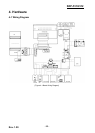
4-3-3 Buzzer and Cash Drawer Circuits
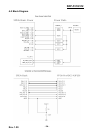
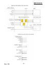
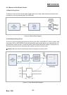
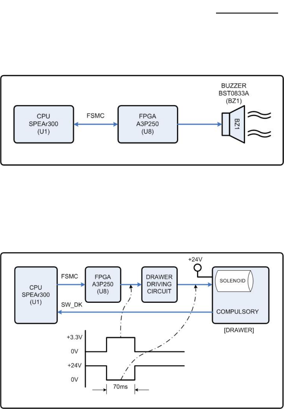
1) Buzzer Driving Circuit
The Buzzer is used to inform several kinds of states which occur under system operating and gives some
information to users by controlling the CPU (SPEAr300)
[Figure 4-6 Buzzer Block Diagram]
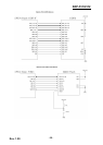
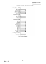
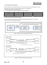
2) Cash Drawer Driving Circuit
The circuit is used for opening cash drawer and driven by the Q301, Q302(2SD2170). When its state is high
level signal, Q301 or Q302 (2SD2170) drive the solenoid to open the cash drawer. As an optional item, we
provide sensor switch (we call it a compulsory switch) which checks the drawer whether it is opened or not.
This sensor switch turns on for the drawer open condition, and turns off for the other.
※ Caution: Make sure that the Cash Drawer solenoid resistance is more than 20Ω.
[Figure 4-7 Cash Drawer Block Diagram]