


Rev. 1.00
- 8 -
SRP-F310/312
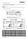
1-2 Connecting the Cables
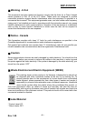
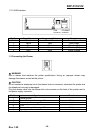
You can connect up the three cables to the printer. They all connect to the connector panel
on the back of the printer, which is shown below:
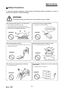
※ NOTE
Before connecting any of the cables, make sure that both the printer and the host are
turned off.
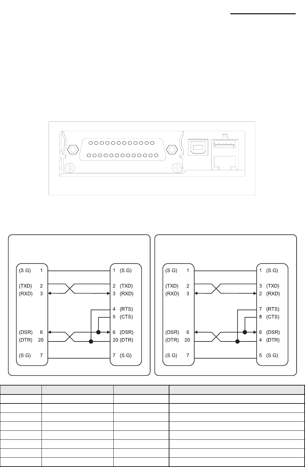
1-2-1 Serial Interface (RS-232C)
※ When the Dip Switch is “ON” on the Serial Interface Board,
DTR and RTS are connected each other.
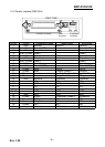
Pin No. Signal name Direction Function
1 FG - Frame Ground
2 TxD Output Transmit Data
3 RxD Input Receive Data
4 RTS Output Ready To Send
5 CTS Input Clear To Send
6 DSR Input Data Set Ready
7 SG - Signal Ground
20 DTR Output Data Terminal Ready
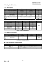
IFE-S TYPE
USB
connector
ETHERNET
connector
Interface connector
PRINTER
SIDE (25P)
HOST
SIDE (25P)
PRINTER
SIDE (25P)
HOST
SIDE (9P)