Page 10
724-746-5500 | blackbox.com
Chapter 2: Overview
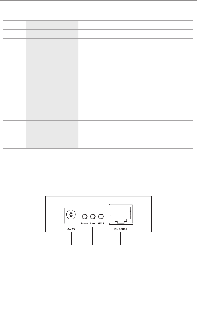
Table 2-1. Transmitter’s components.
Number Component Description
1 Barrel connector Links to 5-VDC power supply
2 Power LED Lights when the unit is receiving power.
3 Link LED
When this LED is ”ON,” an HDBASE-T link connection is
established between the transmitter and the receiver over the
CAT5e/6 cable.
4
HDCP LED
When this LED is ”ON,” video content with HDCP
protection is being transferred.
When the LED is “Blinking,”video content without HDCP is
being transferred.
When the LED is “OFF,” no video is connected.
5 HDBASE-T Connect the transmitter to the receiver using a CAT5e/6 cable.
6 IE port
Connect the extender infrared emitter cable from this port to
the HDMI source to control the source from the viewing
location.
7 HDMI In port Connect the HDMI source to this port.
2.4.2 Receiver
FIgures 2-3 and 2-4 show the front and back panels of the receiver unit. Table 2-2
describes its components.
1 2 3 4 5
Figure 2-3. Receiver’s front panel.


