


AutoDome Power Supply Boxes Cable and Wire Standards | en 33
Bosch Security Systems, Inc. Installation Guide F.01U.250.895 | 1.0 | 2011.08
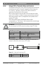
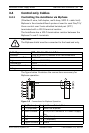
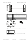
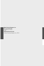
Figure 3.6 Connections for RS485 Operations
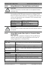
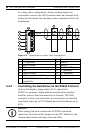
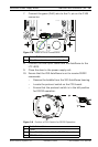
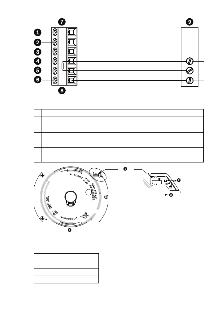
Figure 3.7 Position of CPU Switch for RS485 Operation (camera module
not shown for clarity)
Note: To access the CPU switch you must remove the bubble
from the pendant housing.
1 C- (Biphase) 7 AutoDome Data In/Out
2 C+ (Biphase) 8 P105/P106 Connector in Power Supply
Box
3 Earth Ground 9 Head End RS485
4 RxD 10 Data +
5 TxD 11 Data -
6 Signal Ground 12 Ground
1 Switch Location
2LEDs
3 RS485
4CPU Module
100 Ω