


Chapter 2
2-9
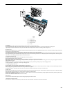
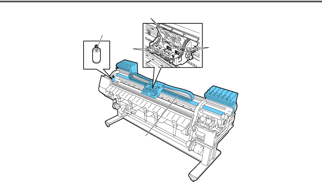
F-2-8
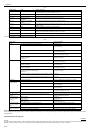
T-2-5
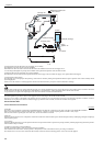
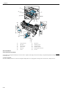
c) Controller
The Carriage relay PCB is connected to the head relay PCB by means of a short flexible cable.
The flexible cable between the main controller and the carriage relay PCB follows up the motion of the carriage together with the tube guide.
A photocoupler encoder mounted in the lower part of the back of the carriage detects a linear scale reading as the carriage moves.
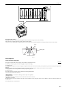
d) Carriage drive
Mechanical misregistrations in the vertical/horizontal and bidirectional print positions of the printhead mounted can be corrected by selecting Adjust Printer from
the main menu to shift the print timing.
A DC-operated carriage motor drives the carriage reciprocally on the platen by way of the carriage belt.
The carriage home position, or the capping position, is detected by the sensor flag on the right side of the carriage and the photointerrupter-based carriage HP sensor
on the right side of the printer. When the linear scale position is set as a reference home position for use in subsequent position control operations, the carriage motor
is driven by a control signal generated from the main controller PCB.
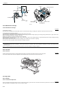
e) Printhead maintenance unit
This printer cleans the printhead with the carriage halted at its home position.
Wiping takes through the rotation of the motor.
Wiper blades mounted on the carriage wipe the printhead while the carriage is halted at its home position.
Wet wiping is carried out for added wiping removal performance, whereby the wiper blades are moistened with glycerin as they are pressed against an absorber
impregnated with glycerin.
Maintenance jet ejection is carried out on the cap, at the maintenance jet tray, borderless printing ink tray and on the paper surface.
A suction operation is carried out by a suction cap in the purge unit.
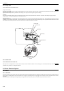
f) Carriage height adjustment unit
The head height is adjusted with the carriage halted at its home position.
The lift motor is driven to rotate the lift shaft within the carriage, in sync with which the lift cams on both sides of the carriage move the head holder up and down,
thereby varying the separation between the face of the printhead and the paper.
The printhead height is detected from the lift cam sensor within the carriage and the distance of rotation of the lift motor.
g) Multi sensor
The multi sensor attached to the lower left part of the carriage consists of four LEDs (red, blue, green, infrared) and two light-receiving sensors to detect the leading
edges and width of paper and skews in it, and to adjust its registration and head height.
The multi sensor standard has a white plate attached to it, so that a reference value can be calculated during carriage height measurement by measuring the intensity
of light reflected upon the white plate.
(Service mode: SERVICE MODE>ADJUST>GAP CALIB)
h) Rail cleaner
The shaft cleaner located in the right rear of the carriage helps keep the main rail clean.
i) Internal unit temperature sensor
One thermistor is installed on the head relay PCB on the back of the head holder to detect the internal unit temperature.
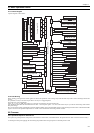
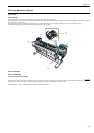
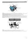
[1] Carriage motor
[2] Printhead fixer lever
[3] Printhead fixer cover
[4] Electrical contact
[5] Ink tube
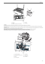
[3]
[1]
[2]
[4]
[5]